
Workpiece grinding method

a technology of workpieces and grinding methods, applied in the direction of grinding drives, grinding heads, manufacturing tools, etc., can solve the problems of prone to fall-off (shedding) of abrasive grits and processing failures, and achieve the effect of low grinding capability

Active Publication Date: 2022-01-20
DISCO CORP
View PDF9 Cites 0 Cited by
  • Summary
  • Abstract
  • Description
  • Claims
  • Application Information

AI Technical Summary

Benefits of technology

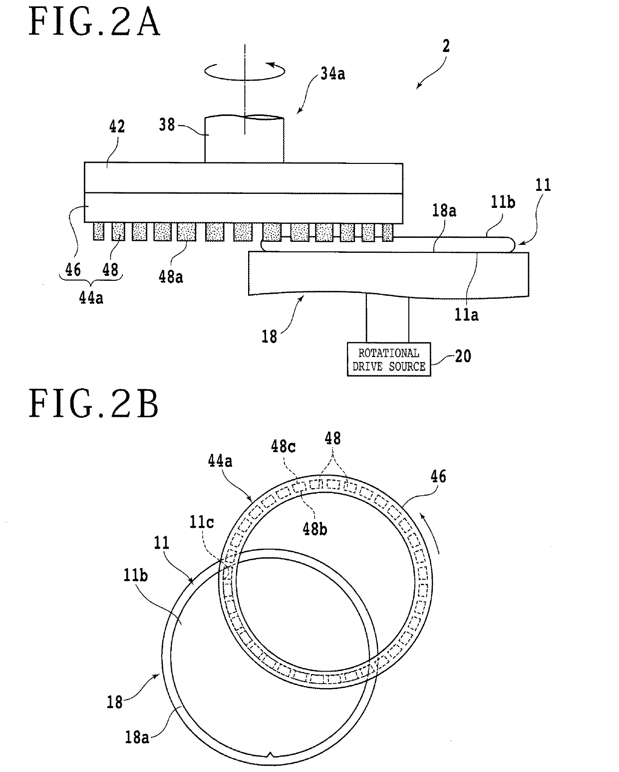
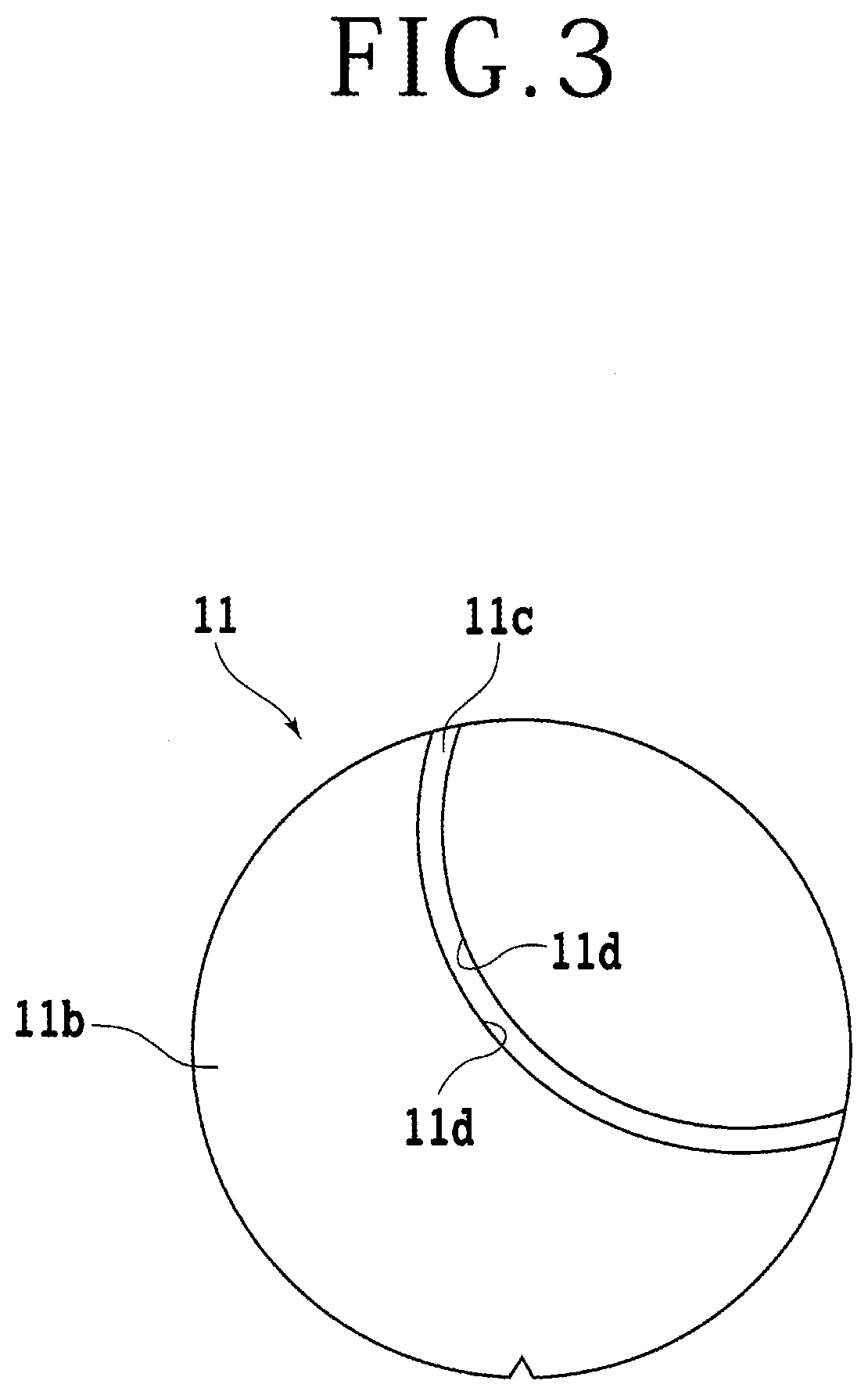
The workpiece grinding method described in this patent involves a process for removing a groove from a workpiece and then grinding the entire back surface of the workpiece. By rotating the spindle without moving the chuck table, a curved groove is formed in the workpiece. The groove is then grinded out using the side surfaces of the grinding stones. This process helps to maintain the grinding capability of the stones and prevents failure of the workpiece during processing. The entire back surface of the workpiece is then ground using the bottom surfaces of the grinding stones, which are in better condition compared to the side surfaces. This reduces the likelihood of processing failures, even if a hard oxide film is formed on the back surface.

Problems solved by technology

If a relatively hard oxide film is formed on the ground surface, for example, fall-off (shedding) of abrasive grits is prone to occur.
In such a case, a longer period of time is needed from the fall-off of abrasive grits until completion of self-sharpening, in other words, a workpiece is ground for a longer period of time in a state that grinding stones have a low grinding capability, so that a processing failure tends to take place.

Method used


Image

  • Workpiece grinding method
  • Workpiece grinding method
  • Workpiece grinding method

Examples


Embodiment Construction

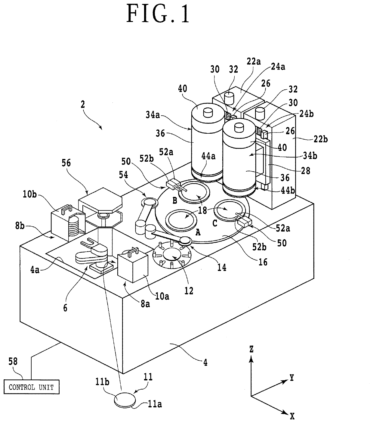
[0018]With reference to the attached drawings, an embodiment of the aspect of the present invention will hereinafter be described. A description will first be made about a configuration example of a grinding machine 2 that can perform the grinding method of this embodiment for a workpiece 11. FIG. 1 is a perspective view depicting the grinding machine 2. In the following description, an X-axis direction (left-right direction), a Y-axis direction (front-rear direction), and a Z-axis direction (grinding feed direction, up-down direction, height direction) intersect one another at right angles. Further, some elements of the grinding machine 2 are illustrated by functional blocks in some of the attached drawings.

[0019]The grinding machine 2 includes a bed 4 that supports or accommodates individual elements. The bed 4 is provided, on a side of an upper surface of a front end section thereof, with a rectangular opening 4a. In the opening 4a, a horizontal articulated robot arm (first trans...


PUM


Abstract

A workpiece grinding method includes a groove formation step, a groove removal step, and a full surface grinding step. In the groove formation step, the workpiece is ground by performing grinding feed of a grinding unit while rotating a spindle without rotation of a chuck table, so that an arcuate groove is formed with a depth not reaching a finish thickness on a side of a back surface of the workpiece. In the groove removal step, rotation of the chuck table is started with the spindle kept rotating, so that the groove is ground at side walls thereof and is removed from the workpiece. In the full surface grinding step, grinding feed of the grinding unit is performed while the spindle and chuck table are rotated, so that the workpiece is ground in an entirety thereof on the side of the back surface until the workpiece has the finish thickness.

Description

BACKGROUND OF THE INVENTIONField of the Invention[0001]The present invention relates to a workpiece grinding method for grinding, with a grinding wheel, a workpiece held on a chuck table.Description of the Related Art[0002]In a manufacturing process of device chips, devices, such as an integrated circuit (IC) or large scale integration (LSI), are formed in regions of a wafer. These regions are defined by a plurality of intersecting lines (hereinafter called “the streets”). By dividing the wafer along the streets, a plurality of device chips each including the devices are manufactured. Such device chips are incorporated in various kinds of electronic equipment such as mobile phones and personal computers. In recent years, there is a growing demand for thinner device chips as a reflection of a move toward downsizing of electronic equipment. A method is hence used to thin a wafer by applying grinding to the wafer before dividing it. For the grinding of the wafer, a grinding machine inc...

Claims


Application Information

Patent Timeline
IPC IPC(8): B24B47/20B24B27/00
CPCB24B47/20B24B27/0076B24B27/0046B24B19/02B24B27/0023B24B27/0069B24B27/0683B24B47/12B24B41/068B24B7/228B24B41/047B24B41/061H01L21/67092
Inventor SUZUKI, YOSHIKAZU
Owner DISCO CORP
Learn More