
Spacer and hard disk drive apparatus

a spacer and hard disk technology, applied in the field of spacer and hard disk drive apparatus, can solve the problems of difficult to remove a spacer, the above-described demands for increasing the storage capacity of hdd apparatuses are not sufficiently satisfied, and the long-term reliability of hdd apparatuses is likely to be impaired, so as to suppress the occurrence of removal failures

Active Publication Date: 2021-03-25
HOYA CORP
View PDF0 Cites 0 Cited by
  • Summary
  • Abstract
  • Description
  • Claims
  • Application Information

AI Technical Summary

Benefits of technology

The present invention aims to provide a spacer and an HDD apparatus that can prevent removal failures when using a gripping jig to remove spacers and magnetic disks during assembly. The technical effect of this invention is to improve the efficiency and reliability of the assembly process of the HDD apparatus.

Problems solved by technology

Currently used magnetic disks are configured to make the float distance between a magnetic head and a magnetic disk extremely small in order to install many magnetic disks in an HDD apparatus, but the above-described demands for increasing the storage capacity of HDD apparatuses are not sufficiently satisfied.
In this case, long-term reliability of the HDD apparatus is likely to be impaired by the generated minute particles.
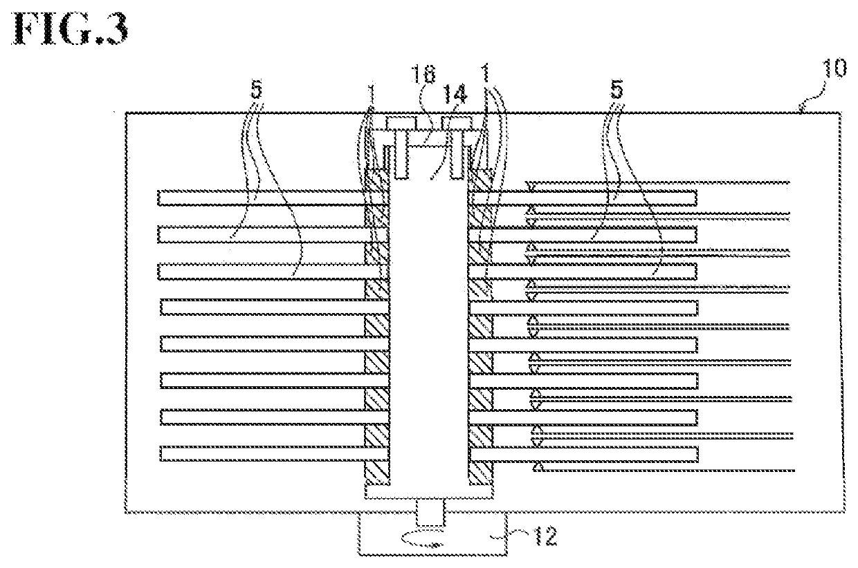
In the assembled HDD apparatus, the magnetic disks and the spacers are strongly pressed in the axial direction of the spindle to come into close contact with each other, and therefore there is a case in which it is difficult to remove a spacer that is adhered to a magnetic disk by gripping an outer circumferential edge surface of the spacer using the gripping jig of the assembly apparatus.
Further, if a removal failure occurs when removing a spacer using the gripping jig, the outer circumferential edge surface of the spacer and the gripping jig rub against each other, and as a result, foreign matter, such as minute particles (particles), may be generated.
Accordingly, the number of spacers to be removed increases, and the number of spacers adhered to magnetic disks also increases, and therefore, when removing the spacers using the gripping jig, a removal failure is more likely to occur and minute particles that cause impairment of long-term reliability of the HDD apparatus are likely to be generated.

Method used


Image

  • Spacer and hard disk drive apparatus
  • Spacer and hard disk drive apparatus
  • Spacer and hard disk drive apparatus

Examples


experimental examples

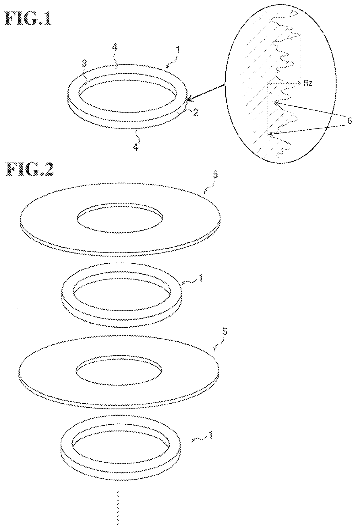
[0061]In order to confirm the effects of the spacer 1 of the embodiment, spacers (Samples 1 to 26) having different surface irregularities in the outer circumferential edge surface 2 were manufactured. First, an outer circumferential edge portion and an inner circumferential edge portion of a ring-shaped blank that was cut out from a glass plate were ground using a formed grindstone to form the outer circumferential edge surface 2, the inner circumferential edge surface 3, and a chamfered surface. Next, the main surfaces 4 were subjected to lapping that was performed using loose abrasive particles including alumina particles, polishing that was performed using loose abrasive particles including ceria particles, and washing. The manufactured spacers had an inner diameter of 25 mm, an outer diameter of 32 mm, and a thickness of 2 mm. The chamfered surface had an angle of 45° and a width in a radial direction of 150 μm, and the specifications of the chamfered surface were common betwee...


PUM

PropertyMeasurementUnit
height surface roughness Rzaaaaaaaaaa
surface roughnessaaaaaaaaaa

Abstract

A ring-shaped spacer is to be arranged in contact with a magnetic disk in a hard disk drive apparatus. A maximum height surface roughness Rz of an outer circumferential edge surface of the spacer is at least 1.5 μm, and the spacer is made of amorphous glass.

Description

CROSS-REFERENCE TO RELATED APPLICATIONS[0001]This is a continuation application of U.S. patent application Ser. No. 16 / 634,079, filed on Jan. 24, 2020, which is a U.S. National stage application of International Patent Application PCT / JP2018 / 032488, filed on Aug. 31, 2018, which, in turn, claims priority to Japanese Patent Application No. 2017-167236, filed in Japan on Aug. 31, 2017, the entire contents of which are hereby incorporated herein by reference.BACKGROUNDField of the Invention[0002]The present invention relates to a ring-shaped spacer to be arranged in contact with a magnetic disk in a magnetic recording hard disk drive apparatus, and a hard disk drive apparatus in which the spacer is used.Background Information[0003]Following the expansion of cloud computing in recent years, many hard disk drive apparatuses (hereinafter referred to as HDD apparatuses) are used in a data center for a cloud in order to increase the storage capacity. Thus, there are demands for increasing t...

Claims


Application Information

Patent Timeline
Patent Type & Authority Applications(United States)
IPC IPC(8): G11B17/028G11B17/038G11B25/04
CPCG11B17/028G11B25/04G11B17/038G11B23/0057G11B25/043G11B17/021
Inventor TAKANO, MASAO
Owner HOYA CORP
Learn More