
Explosive separating joint

a separation joint and explosive technology, applied in the direction of transportation and packaging, weapons, cosmonautic vehicles, etc., can solve problems such as separation failure, and achieve the effect of reducing the risk of separation failur

Active Publication Date: 2019-05-02
NORTHROP GRUMMAN SYST CORP
View PDF0 Cites 5 Cited by
  • Summary
  • Abstract
  • Description
  • Claims
  • Application Information

AI Technical Summary

Benefits of technology

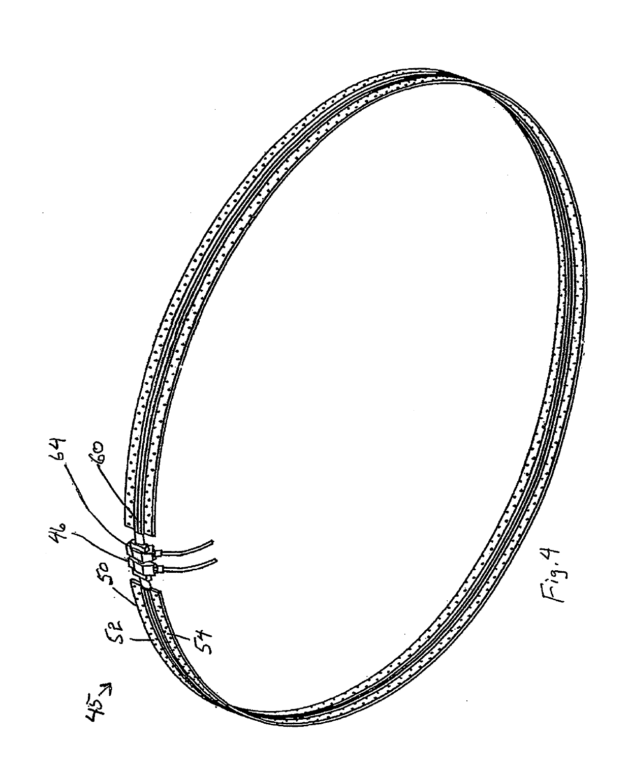
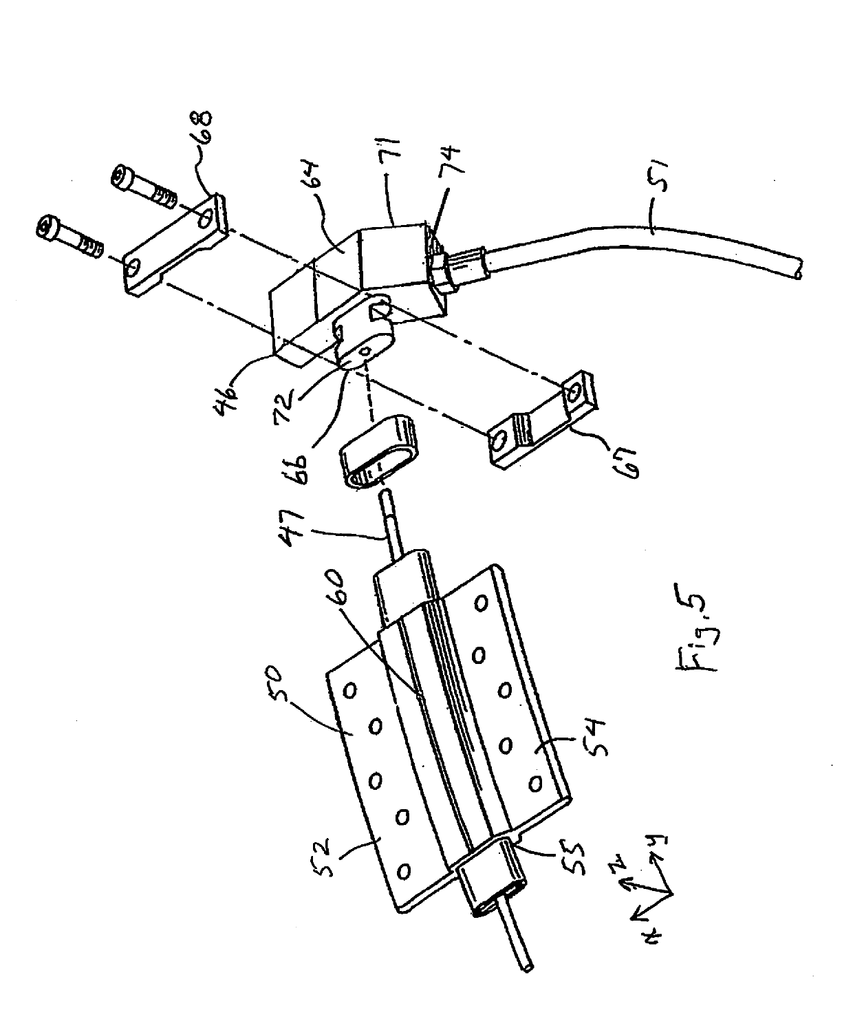
The invention is an explosive separation joint system that provides reliable detonation and separation of the joint. The system uses a manifold to detonate the joint and separate it, but previous detonation manifolds had a problem where the MDF was not tightly constrained and could be affected by thermal, dynamic, and inertial stresses, causing a failure in the detonation train and ultimately affecting the separation of the joint. However, the new invention solves this problem by placing the MDF in a manifold that is constrained inward to stop the MDF but not outward, allowing for some slight compression and minimizing movement of the MDF during extreme conditions. The system also changes the impulse path for initiating detonation and ensures reliable operation. The invention reduces manufacturing costs by reducing the precision required for the joint design and manufacture. Overall, the invention improves the reliability and safety of the explosive separation joint system.

Problems solved by technology

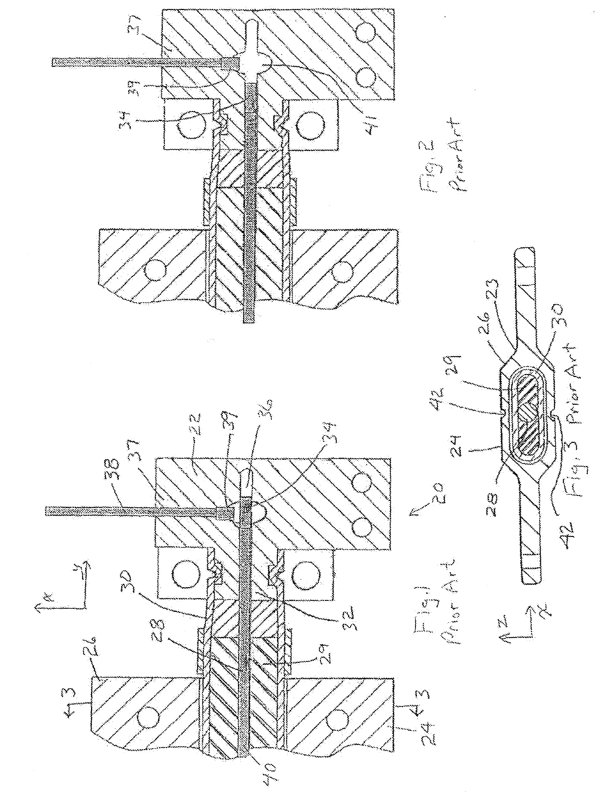
The MDF is not tightly constrained with in the joint and manifold and is subject to thermal, dynamic, and inertial stresses that may move the MDF end with booster out of a critical operation zone of the initiating ordnance, interrupting the detonation train, thereby precluding detonation of the MDF by the initiating ordnance causing a separation failure.

Method used


Image

  • Explosive separating joint
  • Explosive separating joint
  • Explosive separating joint

Examples


Embodiment Construction

[0040]Referring to FIGS. 1 and 3, cross sectional views of an explosive separation joint system 20 having a manifold 22, a joint 23 comprising a pair of separable and unitary joint portions 24, 26, a mild detonating fuse (MDF) 28 supported in an elastomeric material 29 in a flattened metal tube 30 and extends into the manifold at a port 32. The MDF including a MDF booster 34, attached thereto in an open interior 36 and in alignment with an initiating ordnance port 37 and an initiating ordnance (IO) in a tube 38 having an ordnance end tip 39. FIG. 1 shows the IO end tip in alignment with the MDF booster such that when the IO is detonated the end tip sends an axial pulse toward the MDF booster which detonates the MDF line portion 40 causing expansion of the flattened metal tube 30, fracturing apart the unitary joint portions at the grooves 42.

[0041]Referring to FIG. 2, the inventors have discovered a failure path whereby the MDF moves in the manifold such as due to the extreme conditi...


PUM


Abstract

An explosive separation joint system having an expandable tube containing a mild detonating fuse (MDF) in separable portions of the joint. The MDF extends into a detonation manifold at a first port, an end of the MDF having booster bonded thereto. An external initiating ordnance transfer line enters the manifold at an initiating ordnance (IO) port, has an IO end tip and provides a detonation impulse train where each detonating component is axially aligned within a passageway with the next detonating component. In embodiments, particular detonating components of the detonation train are fixed in place where other detonating components are movable. Each detonating component that is not in direct contact with a preceding detonating component in the detonation train is in direct linear access.

Description

[0001]This application claims the benefit of U.S. Provisional Application No. 62 / 579,020, filed Oct. 30, 2017, the contents of which are herein incorporated by reference.BACKGROUND OF THE INVENTION[0002]The invention relates to explosive separation joint systems such as utilized for separation of launch vehicles. Such joints utilize mild detonating fuses (MDF) that extend from the separable portions into a detonation manifold and are initiated by an external initiating ordnance such as flexible confined detonating cord also extending into the detonation manifold. The MDF having an end with a booster attached thereto. The initiating ordnance positioned to provide an impulse perpendicularly to the axis of the MDF and being in alignment with the MDF booster. The MDF may be in a flattened steel tube and upon detonation of the MDF by the initiating ordnance the steel tube expands to a circular cross sectional configuration that ruptures or causes disengagement of separable portions of th...

Claims


Application Information

Patent Timeline
IPC IPC(8): F42B15/38B64G1/64F42B3/093
CPCF42B15/38B64G1/645F42B3/093B64G1/641B64G1/6455
Inventor COHEN, DAVID BRUCEDOYLE, JOHN THOMASHAYNIE, RICHARD MARKHARRINGTON, PAUL JESSEBURNSIDE, GARY RONALD
Owner NORTHROP GRUMMAN SYST CORP
Learn More