Turbine system having more failure resistant rotors and repair welding of low alloy ferrous turbine components by controlled weld build-up

a technology of ferrous turbine components and turbine systems, which is applied in the direction of parallel air flow wind motors, wind turbines with perpendicular air flow, electric beam welding apparatus, etc., can solve problems such as loss of strength, reduce failure risk, reduce weld stress and cracking, and improve weld integrity. , the effect of reducing the risk of failur

Inactive Publication Date: 2002-02-26
SIEMENS POWER GENERATION
View PDF42 Cites 31 Cited by
  • Summary
  • Abstract
  • Description
  • Claims
  • Application Information

AI Technical Summary

Benefits of technology

Improved turbine systems including more failure resistant rotors and novel methods for repairing worn surfaces of steam turbines, especially high pressure turbine rotors are disclosed. The methods include welding procedures and heat treatments that minimize weld stresses and cracking. The procedures employed substantially reduce the risk of failure in ferrous Cr-Mo-V base metals of high-pressure, high temperature rotors and discs commonly found in steam turbines. This invention presents an improvement over welding forged fastenings to rotors, since welder accessibility and weldment integrity are improved. These features are particularly important with respect to high pressure, (HP), turbine components, such as rotors, which have been known to operate at pressures over 2400 psi and temperatures over 1000.degree. F.

Problems solved by technology

This loss in strength occurs, to a greater extent, when a stress transverse to the weld is applied, for example, high and low cycle fatigue, tensile, or creep-to-rupture.

Method used


Image

  • Turbine system having more failure resistant rotors and repair welding of low alloy ferrous turbine components by controlled weld build-up
  • Turbine system having more failure resistant rotors and repair welding of low alloy ferrous turbine components by controlled weld build-up
  • Turbine system having more failure resistant rotors and repair welding of low alloy ferrous turbine components by controlled weld build-up

Examples


Embodiment Construction

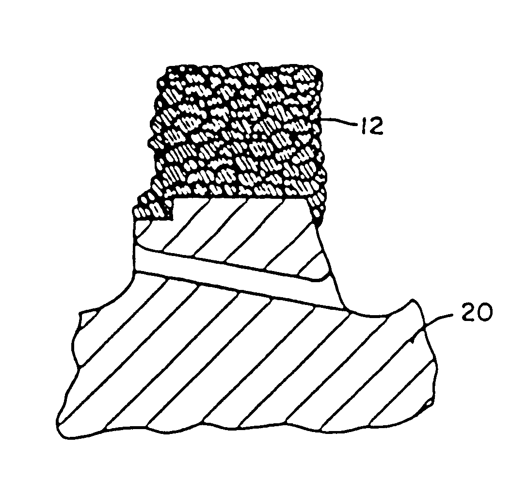
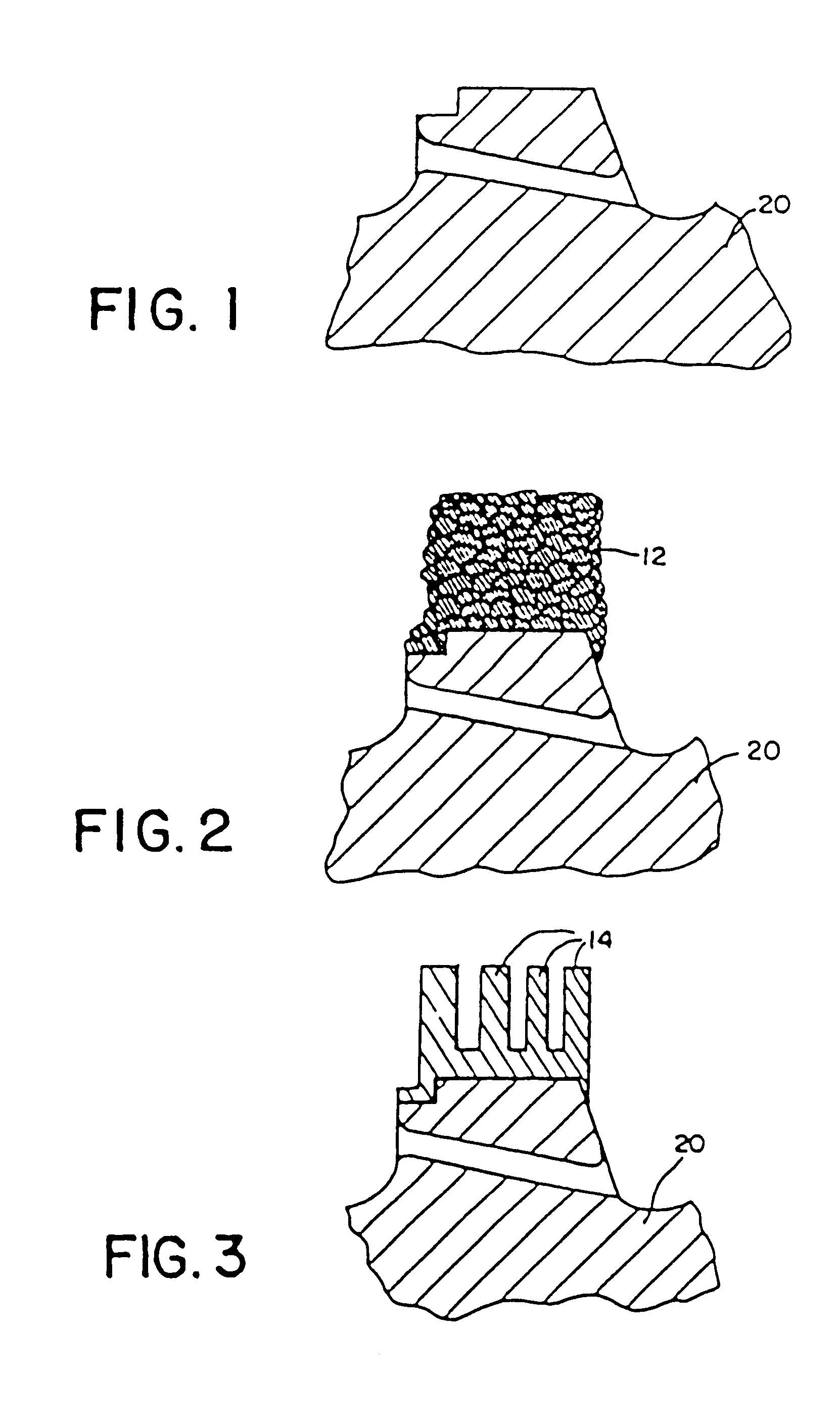
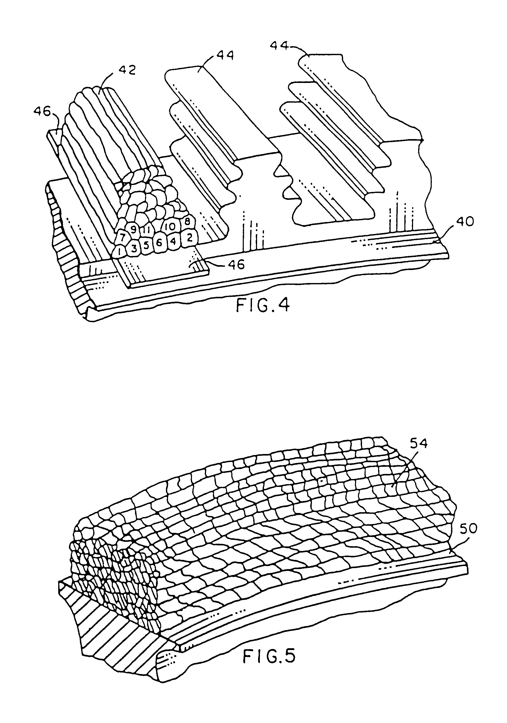
The novel methods of repairing worn surfaces of ferrous turbine components of this invention include providing a ferrous turbine component 20, 40, or 50 having Cr, Mo and V alloying ingredients. These turbine components 20, 40, or 50 include worn surfaces, however it is expected that new components can be manufactured using the methods disclosed herein. The repairing procedure includes depositing a first layer of weld metal the worn surface of the component thereby producing a heat-affected zone in that component. The procedure next deposits a second layer of weld metal on top of the first layer. This second layer is deposited with a greater amount of heat than the depositing of the first layer for tempering at least a portion of the heat affected zone produced by the first depositing step. As used herein, the term "tempering" refers to the process wherein the heat-affected zone of the base metal is re-heated and then cooled to relieve internal stress and reduce its hardness.

By care...


PUM

PropertyMeasurementUnit
temperature Charpy toughnessaaaaaaaaaa
yield strengthaaaaaaaaaa

Abstract

System for repairing worn surfaces of steam turbine components and especially high pressure turbine rotors, are disclosed. These systems include depositing a first layer of weld metal on a worn surface of the component, whereby a heat-affected zone is created. A second layer of weld metal is then deposited over the first layer using a greater amount of heat to temper at least a portion of the heat-affected zone produced by the first layer. The preferred embodiments include the use of gas tungsten arc welding for providing fine-grain size and more creep resistance, especially in the weld and heat-affected zone. The resulting build-up can be machined, for example into a blade fastening to produce a component having properties equal to or better than the base-metal alloy. The invention also provides a longer lasting turbine system, including rotors which have serrated steeples that are more resistant to failure.

Description

CROSS REFERENCE TO RELATED APPLICATIONSThis application is related to co-pending application Ser. No. 168,097, filed Mar. 14, 1988, in the names of E. Clark and D. R. Amos, entitled "Repair Welding Low Alloy Turbine Components", which is assigned to the assignee of this application and which is hereby incorporated by reference.This application is also related to co-pending application Ser. No. 092,851, filed Aug. 24, 1987, in the names of R. T. Ward and J. M. Butler, entitled "Repair of High-Pressure Turbine Rotors By Ring Welding", which is assigned to the assignee of this application and which is herein incorporated by reference.This application is also related to application Ser. No. 763,744, filed Aug. 8, 1985, in the names of R. E. Clark and D. R. Amos, entitled "Method for Repairing A Steam Turbine Or Generator Rotor", now U.S. Pat. No. 4,633,544, issued Jan. 6, 1987, which is assigned to the assignee of this application and which is herein incorporated by reference.This appli...

Claims


Application Information

Patent Timeline
Patent Type & Authority Patents(United States)
IPC IPC(8): B23K26/00B23K15/00B23K26/34B23K9/04B23K9/23F01D5/00F01D5/30F01D25/00
CPCB23K9/046B23K15/0086B23P6/007F01D5/005B23K26/3206B23K26/345B23K35/0255B23K35/0272B23K35/308C22C38/12C22C38/18C22C38/22C22C38/24B23K9/23Y10T29/49746B23K2201/001Y10T29/49318B23K26/32B23K26/342B23K2101/001B23K2103/50B23K9/04
Inventor CLARK, ROBERT E.AMOS, DENNIS R.
Owner SIEMENS POWER GENERATION
Why Eureka
Try Eureka