
Integrated circuit chip and flip chip package having the integrated circuit chip

a technology of integrated circuit chip and flip chip, which is applied in the direction of semiconductor devices, semiconductor/solid-state device details, electrical apparatus, etc., can solve the problems of concentration generating cracks on the surface of wiring, process damage to the wirings of the ic chip, and mechanical fracture of the flip chip packag

Active Publication Date: 2011-04-07
SAMSUNG ELECTRONICS CO LTD
View PDF16 Cites 17 Cited by
  • Summary
  • Abstract
  • Description
  • Claims
  • Application Information

AI Technical Summary

Benefits of technology

[0014]Accordingly, there is still a need for an improved manufacturing process in which the bump structure is formed on the supplementary electrode pad without any damage to the wirings under the supplementary electrode pad.
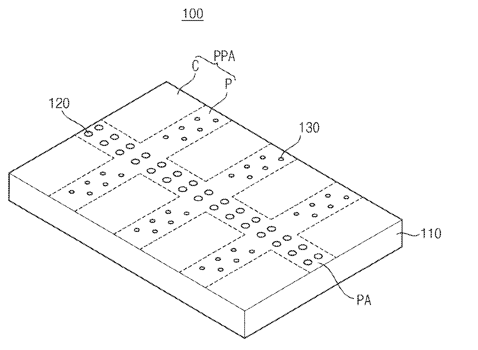
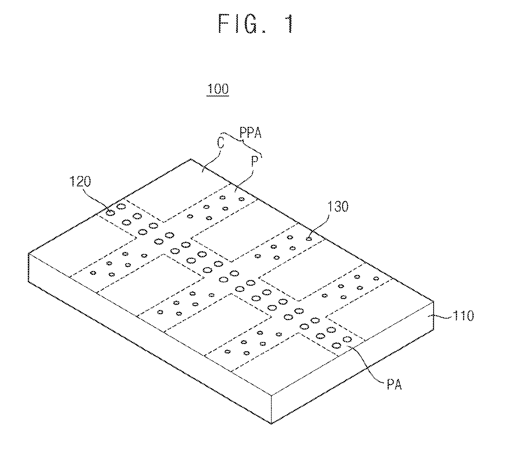
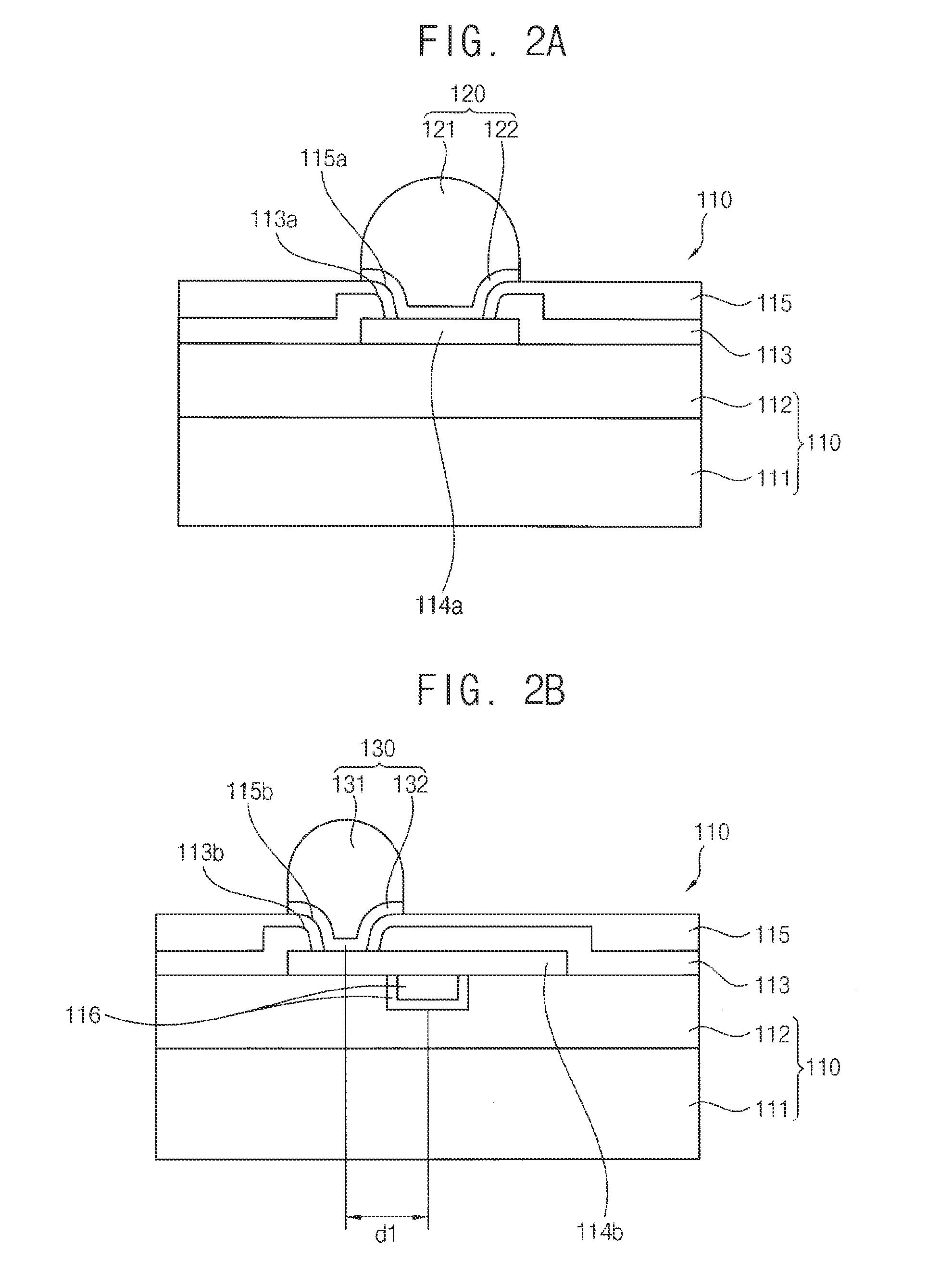
[0033]According to example embodiments of the present general inventive concept, the bump structure may make contact with the electrode pad in cell and peripheral areas of the IC chip in such a configuration that the bump structure may be shifted from the underlying wiring line by a gap distance. Therefore, although the internal stresses of the IC chip may be varied according to external impacts caused by the installation of external electronic appliances, bonding of the IC chip and the mounting substrate and the formation of the bump structure, the internal stresses may be sufficiently prevented from being concentrated to the wiring line, to thereby minimize the crack and the peeling on the wiring line in the IC chip. In addition, the electrode pad and the bump structure may make contact with a number of contact points, to thereby improve contact reliability of the bump structure. Accordingly, the product reliability of the IC chip and the flip chip package including the IC chip may be significantly improved by the shift of the bump structure from the wiring line in the pseudo pad area.

Problems solved by technology

However, there have been problems of process damage to the wirings of the IC chip and mechanical fracture of the flip chip package due to stress concentration to the wirings of the IC chip, since the supplementary electrode pads are positioned over the wirings of the IC chip contrary to the main electrode pads that are arranged in the pad area of the IC chip.
The stress concentration may generate cracks on a surface of the wiring and a peeling failure against the wiring.

Method used


Image

  • Integrated circuit chip and flip chip package having the integrated circuit chip
  • Integrated circuit chip and flip chip package having the integrated circuit chip
  • Integrated circuit chip and flip chip package having the integrated circuit chip

Examples


Embodiment Construction

[0046]Various example embodiments will be described more fully hereinafter with reference to the accompanying drawings, in which example embodiments of the present general inventive concept are illustrated. The present invention may, however, be embodied in many different forms and should not be construed as limited to the example embodiments set forth herein. Rather, these example embodiments are provided so that this disclosure will be thorough and complete, and will fully convey the scope of the present invention to those skilled in the art. In the drawings, the sizes and relative sizes of layers and regions may be exaggerated for clarity.

[0047]It will be understood that when an element or layer is referred to as being “on,”“connected to” or “coupled to” another element or layer, it can be directly on, connected or coupled to the other element or layer or intervening elements or layers may be present. In contrast, when an element is referred to as being “directly on,”“directly co...


PUM


Abstract

In an integrated circuit (IC) chip and a flip chip package having the same, no wiring line is provided and the first electrode pad does not make contact with the wiring line in a pad area of the IC chip. Thus, the first bump structure makes contact with the first electrode regardless of the wiring line in the pad area. The second electrode pad makes contact with the wiring line in a pseudo pad area of the IC chip. Thus, the second bump structure in the pseudo pad area makes contact with an upper surface of the second electrode at a contact point(s) spaced apart from the wiring line under the second electrode.

Description

CROSS-REFERENCE TO RELATED APPLICATIONS[0001]This application claims priority under 35 U.S.C. §119(a) from Korean Patent Application No. 10-2009-0093968, filed on Oct. 1, 2009, in the Korean Intellectual Property Office, the disclosure of which is incorporated herein in its entirety by reference.BACKGROUND[0002]1. Field of the Invention[0003]Example embodiments of the present general inventive concept relate to a semiconductor device and a method of manufacturing the same, and more particularly, to an integrated circuit (IC) chip including a bump structure and a method of manufacturing the same and a flip chip package having the IC chip and a method of manufacturing the same.[0004]2. Description of the Related Art[0005]Information telecommunication (IT), computer, and display industries have been rapidly developed in recent times and thus electronic components for the IT equipment, the computer systems, and the display apparatuses usually require much higher capacity with much lower...

Claims


Application Information

Patent Timeline
Patent Type & Authority Applications(United States)
IPC IPC(8): H01L23/48
CPCH01L24/11H01L2224/05124H01L2924/01013H01L2924/01015H01L2924/01029H01L2924/01033H01L2924/01047H01L2924/01078H01L2924/01082H01L2924/14H01L2924/19041H01L2224/05569H01L2224/05011H01L24/03H01L24/05H01L24/06H01L24/13H01L2224/02125H01L2224/03464H01L2224/05018H01L2224/05558H01L2224/05655H01L2224/06051H01L2224/13022H01L2224/131H01L2224/13116H01L2224/1403H01L2924/01006H01L2924/014H01L2224/05572H01L2224/13099H01L2924/0002H01L24/12H01L2224/0401H01L23/49816H01L2224/16225H01L2224/16227H01L2224/73204H01L2924/00013H01L2224/05147H01L2924/00014H01L2924/0105H01L2224/13599H01L2224/05599H01L2224/05099H01L2224/29099H01L2224/29599H01L2224/05552H01L2924/15788H01L2924/181H01L2224/13018H01L2224/05556H01L2224/02123H01L2924/00H01L2924/00012
Inventor PARK, JIN-WOOAHN, EUN-CHULSHIN, DONG-KILKANG, SUN-WONLEE, JONG-HO
Owner SAMSUNG ELECTRONICS CO LTD
Learn More