Imaging optical system, image projection apparatus, and imaging apparatus
- Summary
- Abstract
- Description
- Claims
- Application Information
AI Technical Summary
Benefits of technology
Problems solved by technology
Method used
Image
Examples
first embodiment
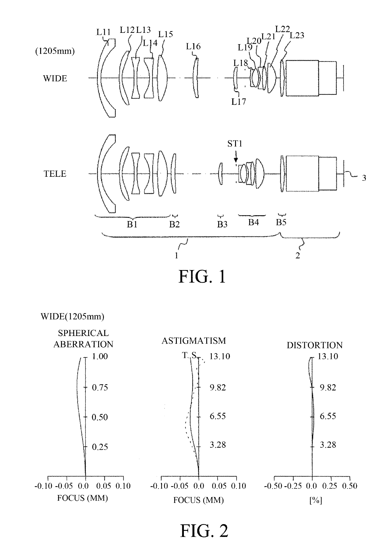
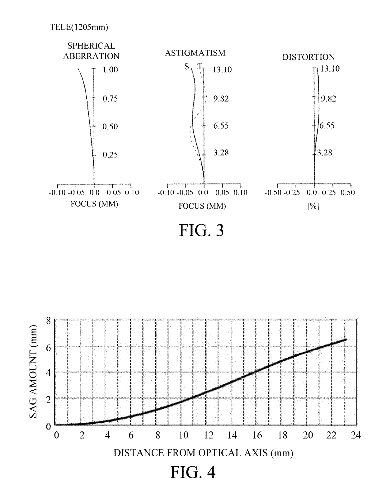
[0023]Referring now to FIG. 1, a description will be given of a principle and effects of the present invention. FIG. 1 illustrates a simplified configuration of an image projection apparatus using the imaging optical system (with a projection distance of 1205 mm) according to this embodiment as a projection lens. The image projection apparatus includes, in order from an enlargement conjugate side, an imaging optical system 1, a prism unit 2, and an image display element 3. FIG. 2 is a longitudinal aberration diagram of the imaging optical system 1 at a wide-angle end. FIG. 3 is a longitudinal aberration diagram at a telephoto end of the imaging optical system 1.
[0024]The imaging optical system 1 includes, in order from the enlargement conjugate side, a front unit, a diaphragm ST1, and a rear unit. The front unit includes, in order from the enlargement conjugate side, a first lens unit B1 that is fixed in a magnification variation and has a negative refractive power, a second lens un...
second embodiment
[0045]This embodiment is different from the first embodiment in that a ratio of the refractive power of the third lens to that of the second lens is larger, and the number of aspheric lenses in the first lens unit is reduced by one. FIG. 8 illustrates a simplified configuration of an image projection apparatus using the imaging optical system (with a projection distance 1205 mm) according to this embodiment as a projection lens. The image projection apparatus includes, in order from the enlargement conjugate side, an imaging optical system 21, a prism unit 22, and an image display element 23. FIG. 9 is a longitudinal aberration diagram of the imaging optical system 21 at a wide-angle end. FIG. 10 is a longitudinal aberration diagram of the imaging optical system 21 at a telephoto end.
[0046]The imaging optical system 21 includes, in order from the enlargement conjugate side, a front unit, a diaphragm ST2, and a rear unit. The front unit includes, in order from the enlargement conjuga...
third embodiment
[0050]This embodiment changes a surface shape of the aspheric lens in the imaging optical system according to the first embodiment. FIG. 11 illustrates a simplified configuration of an image projection apparatus using the imaging optical system (with a projection distance 1205 mm) according to this example as a projection lens. The image projection apparatus includes, in order from the enlargement conjugate side, an imaging optical system 31, a prism unit 32, and an image display element 33. FIG. 12 is a longitudinal aberration diagram of the imaging optical system 31 at a wide-angle end. FIG. 13 is a longitudinal aberration diagram at a telephoto end of the imaging optical system 31.
[0051]The imaging optical system 31 includes, in order from the enlargement conjugate side, a front unit, a diaphragm ST3, and a rear unit. The front unit includes, in order from the enlargement conjugate side, a first lens unit B31 that is fixed in the magnification variation and has a negative refract...
PUM
 Abstract
Description
Claims
Application Information
 - R&D
- Intellectual Property
- Life Sciences
- Materials
- Tech Scout
- Unparalleled Data Quality
- Higher Quality Content
- 60% Fewer Hallucinations
Browse by: Latest US Patents, China's latest patents, Technical Efficacy Thesaurus, Application Domain, Technology Topic, Popular Technical Reports.
© 2025 PatSnap. All rights reserved.Legal|Privacy policy|Modern Slavery Act Transparency Statement|Sitemap|About US| Contact US: help@patsnap.com


