Touch panel and display device comprising same

Active Publication Date: 2019-05-02
VTS TOUCHSENSOR CO LTD
View PDF0 Cites 4 Cited by
  • Summary
  • Abstract
  • Description
  • Claims
  • Application Information

AI Technical Summary

Benefits of technology

The present invention aims to provide a touch panel that allows for a small design load and high degree of freedom in pattern design without generating moire. This allows for a repeat arrangement of electrodes and reduces design load, resulting in a touch panel that is not affected by moire and a display device comprising the same.

Problems solved by technology

However, these transparent materials have high resistance so there are problems in that this leads to a reduction in detection sensitivity when such materials are used in a touch panel having a large screen, and it has become necessary to use low-resistance materials.
However, as indicated above, the node size is determined by the size of the active area of the touch panel and the number of pins in the integrated circuit forming part of the touch panel, so it is not a simple matter to obtain design conditions (pitch and angle of inclination) enabling a repeat arrangement while avoiding moiré.
Furthermore, conditions relating to moire have become more stringent due to the reduced size of nodes because of higher resolution in recent display devices, the increase in clear display devices that have not been subjected to antiglare treatment, and common design requirements for display devices having different resolutions, and there are an increasing number of cases in which it is becoming more difficult to find design conditions enabling repetition while avoiding moire.
Meanwhile, in order to provide a design such that moire is avoided without the use of a repeating arrangement, it is necessary to design the mesh pattern over the whole surface of the active area, so there are problems in that the data volume increases and the design load increases, which leads to higher costs and lower producibility.

Method used


Image

  • Touch panel and display device comprising same
  • Touch panel and display device comprising same
  • Touch panel and display device comprising same

Examples


Embodiment Construction

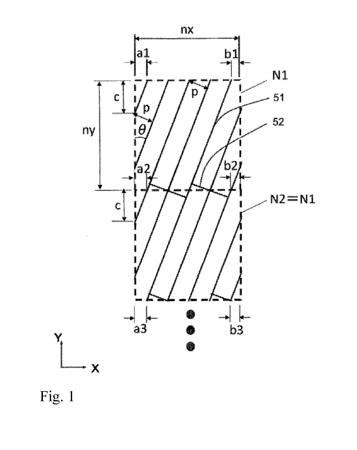
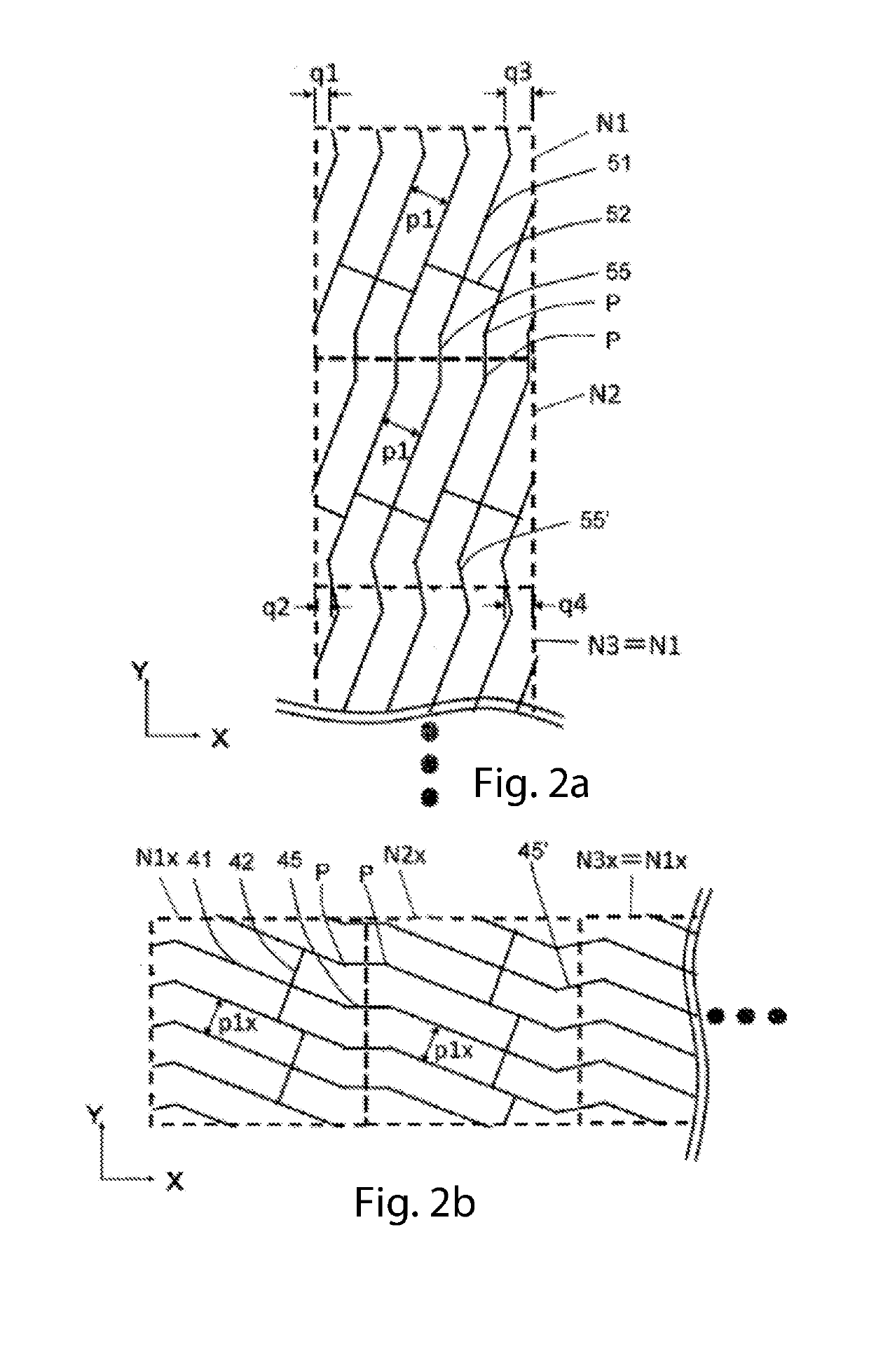
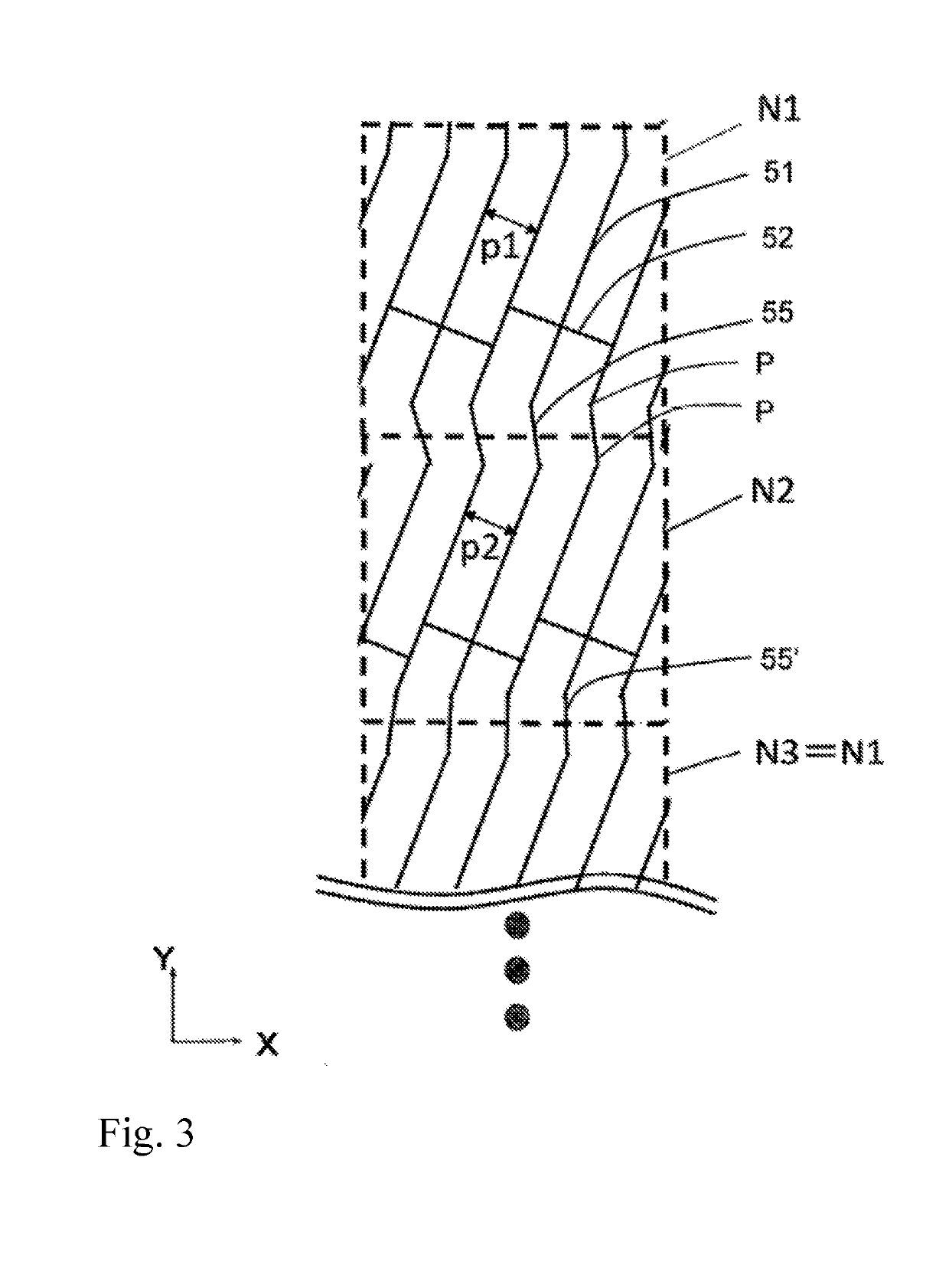
[0044]Modes of embodiment of the touch panel and display device comprising same according to the present invention will be described below with the aid of the drawings, and constituent elements which are the same bear the same reference symbols unless there is a reason otherwise based on practical convenience. Furthermore, the size and proportions of constituent elements may be exaggerated in the drawings in order to make the drawings easier to understand, and the number of constituent elements may also be reduced in the drawings. Furthermore, the present invention is not limited to the following modes of embodiment without any other modification, and the present invention may be embodied in variant forms provided that such forms do not depart from the substance of the present invention.

[0045]The reason for which an arrangement of electrode wires in which the same pattern is repeated in one node unit is subject to constraints in terms of pitch and angle of inclination, in accordance...


PUM


Abstract

A touch panel enabling a repeat arrangement with a small design load, and a mesh pattern with a high degree of freedom and does not generate moire, and a display device comprising same. A touch panel in which a drive electrode pattern / sensing electrode pattern include: first main electrode wires / second main electrode wires constituting line segments having a linear shape extending along a first wire direction / second wire direction; and first auxiliary electrode wires / second auxiliary electrode wires constituting line segments having a linear shape extending along the second wire direction / first wire direction and joining the first main electrode wires / second main electrode wires, and respective end points of the first main electrode wires / second main electrode wires are connected to end points of the closest first main electrode wire / second main electrode wire in adjacent nodes, by connecting wires having a different angle of inclination from the first main electrode wires / second main electrode wires.

Description

CROSS-REFERENCE TO RELATED APPLICATIONS[0001]This application claims priority of Japanese Patent Application Serial No. JP 2017-209 143 filed Oct. 30, 2017, pursuant to 35 U.S.C. 119(a)-(d), the content of which is incorporated herein by reference in its entirety as if fully set forth herein.FIELD OF THE INVENTION[0002]The present invention relates to a touch panel provided with a plurality of electrodes comprising a plurality of electrode wires, and to a display device comprising same.BACKGROUND OF THE INVENTION[0003]Touch panel devices are widely used nowadays as an input means. A touch panel device comprises a touch panel sensor, a control circuit for identifying a contact position, wiring and a flexible printed circuit board (FPC). In many cases, a touch panel device is used as an input means for various devices (e.g., smartphones, ticket machines, ATM devices and gaming devices) having an incorporated display device such as a liquid crystal display or an organic EL display. In ...

Claims


Application Information

Patent Timeline
IPC IPC(8): G06F3/041G06F3/044G06F3/047
CPCG06F3/0416G06F3/0412G06F3/044G06F3/047G06F3/0445G06F3/0446G06F3/04164
Inventor SAKAMOTO, TAROHARADA, TAKAHIRO
Owner VTS TOUCHSENSOR CO LTD
Why Eureka
Try Eureka