Stun grenade and method for production thereof

a technology of grenade and grenade shell, which is applied in the field of grenade shell, can solve the problems of fragment formation, ineffective effect charge, and risk of injury

Inactive Publication Date: 2019-05-09
RHEINMETALL WAFFE MUNITION GMBH
View PDF0 Cites 0 Cited by
  • Summary
  • Abstract
  • Description
  • Claims
  • Application Information

AI Technical Summary

Benefits of technology

[0012]According to an exemplary embodiment of the invention, the flash charge containers are produced separately from the main bodies of the stun grenades and also stored separately therefrom. This dispenses with keeping the stun grenades in a specific position during bonding of the stun grenade. A further advantage of the present invention is in avoiding the formation of fragments when igniting the flash charge container. In conventional stun grenades, fragments are formed by the fact that the adhesive and the cardboard disks which are used in conventional stun grenades are expelled as they burn up and represent a risk of injury.
[0013]The flash charge container is designed as a separate container, into which at least one effect charge can be inserted. Such a container is configured to be watertight in order to prevent the penetration of water and thus the effect charge becoming ineffective.
[0014]Suitable as an ignition device are mechanical or manual devices and also automatic ignition methods in which the ignition device can be ignited electrically or chemically, by time fuses or under remote control.
[0015]The effect charge in the flash charge containers can cause optical and / or acoustic effects here, wherein this is done by burning up the effect charge. For this purpose, the flash charge container in which the effect charge is located is configured such that, following the introduction into the recess in the stun grenade, it can be ignited by the latter by means of the ignition device. For this purpose, the flash charge container preferably has an ignition possibility by means of which it can be ignited via the ignition device in the stun grenade. For example, the ignition device of the flash charge bowl can be made of combustible material in order to be ignited directly. For this purpose, the container of the effect charge itself can also be made of combustible material in order to ensure the ignition possibility. The ignition possibility can, however, also include merely a transfer of heat from the ignition device of the stun grenade to the effect charge.
[0016]The flash charge container can have at least one opening, through which the effect charge can be inserted into the flash charge container. This enables automatic filling of the flash charge container. In order to ensure the water-tightness of the flash charge container, the flash charge container in a special embodiment is closed by a cover and / or attachment which, following filling, produces the water-tightness. Here, coverings, stickers or encapsulations can be used as an attachment. A diaphragm, through which the flash charge container is filled and which seals off the flash charge container is likewise conceivable. Likewise, to produce the water-tightness, the flash charge container can be formed of a bowl which is closed by a cover following filling. The upper side of the bowl then represents the opening. As a result of the watertight configuration of the flash charge container, it is thus possible to store the same separately from the main body of the stun grenade until assembly in the event of use.
[0017]The flash charge container can be configured as a single bowl as a container or as a coherent unit comprising multiple bowls as containers. In the latter case, the container of the flash charge container then includes multiple bowls joined together as containers.

Problems solved by technology

In conventional stun grenades, fragments are formed by the fact that the adhesive and the cardboard disks which are used in conventional stun grenades are expelled as they burn up and represent a risk of injury.
Such a container is configured to be watertight in order to prevent the penetration of water and thus the effect charge becoming ineffective.

Method used


Image

  • Stun grenade and method for production thereof
  • Stun grenade and method for production thereof
  • Stun grenade and method for production thereof

Examples


Embodiment Construction

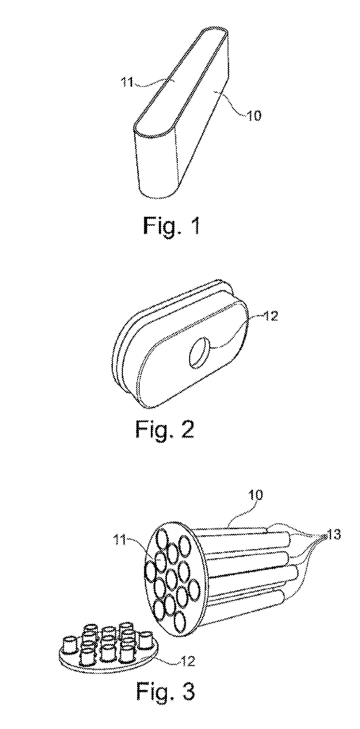
[0038]FIG. 1 shows a bowl as an unclosed flash charge container 10 according to the invention as a separate container, which has an opening 11 toward the upper side. Through this opening 11, the flash charge container 10 can be filled with an effect charge. It is likewise possible to put multiple effect charges into a flash charge container 10. In this case, multiple effects can be triggered with a time offset as a flash charge container 10 burns up.

[0039]The flash charge containers 10 are produced separately from the main bodies 22 of the stun grenades 20 and can also be stored separately from the main bodies 22 of the stun grenades 20 until final assembly in the event of use.

[0040]FIG. 2 shows a cover 12 according to the invention for sealing off the flash charge container 10. Here, the flash charge container comprises a bowl and a cover. Following filling of the bowl with the effect charges, said bowl is closed in a watertight manner by a cover 12. The water-tightness is a precon...


PUM


Abstract

A stun grenade for repelling or defending against threats, and to a method for assembling the stun grenade. For this purpose, the main bodies of the stun grenades are produced separately from the flash charge containers. The flash charge containers are designed as at least one container for this purpose, which can be filled with at least one effect charge via an opening. The flash charge containers are then closed water-tight. The main bodies of the stun grenades can likewise be produced separately and comprise at least one cut-out for inserting the flash charge containers into the stun grenade. Thus, in case of use, the stun grenades can be assembled by mounting at least one flash charge container in the main body.

Description

[0001]This nonprovisional application is a continuation of International Application No. PCT / EP2017 / 064155, which was filed on Jun. 9, 2017, and which claims priority to German Patent Application No. 10 2016 111 947.4, which was filed in Germany on Jun. 30, 2016, and which are both herein incorporated by referenceBACKGROUND OF THE INVENTIONField of the Invention[0002]The present invention relates to a stun grenade for repelling or defending against threats, and a method for assembling the stun grenade. Such stun grenades are used, amongst other things, for support during police and military operations. They can be designed as a throwing body or else as a projectile. Therefore, they can be ignited manually or semi-automatically, possibly also with a time delay.Description of the Background Art[0003]A stun grenade comprises a main body with a corresponding ignition device and at least one effect charge, which can be ignited by the ignition device. Ignition devices of this type are suf...

Claims


Application Information

Patent Timeline
Patent Type & Authority Applications(United States)
IPC IPC(8): F42B27/00F42B12/42
CPCF42B27/00F42B12/42F42B5/145F42B8/26F42B12/36
Inventor HABEL, FRANKKOSCHMIEDER, MATTHIAS
Owner RHEINMETALL WAFFE MUNITION GMBH
Why Eureka
Try Eureka