Method for thermally disinfecting a centrifuge

Active Publication Date: 2019-05-16
GEA MECHANICAL EQUIP
View PDF5 Cites 0 Cited by
  • Summary
  • Abstract
  • Description
  • Claims
  • Application Information

AI Technical Summary

Benefits of technology

This patent describes a way to clean a centrifuge, which is a machine used to process products by spinning them. The method uses heat to kill germs on the surface of the centrifuge. This helps to make sure that the products being processed are safe and free from harmful bacteria.

Problems solved by technology

This requires corresponding calculations, materials, verification etc., which significantly increase the costs of the separator.

Method used


Image

  • Method for thermally disinfecting a centrifuge

Examples


Embodiment Construction

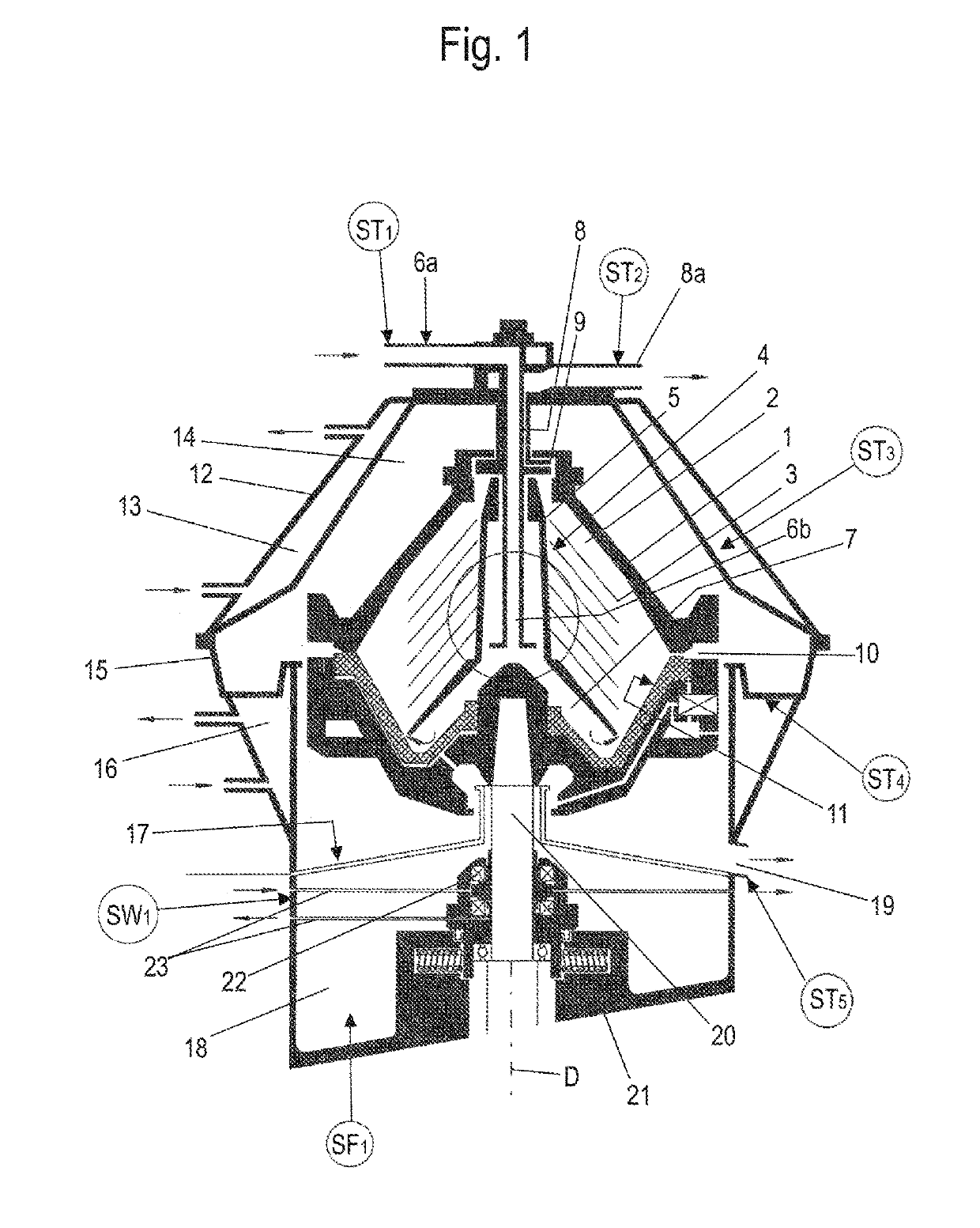
[0015]FIG. 1 shows a centrifuge, in this case a separator, which has a rotatable drum 1. Here, this drum 1 is of double-cone design.

[0016]The drum 1 has a vertical rotation axis D. Arranged in the conical or, in this case, even double-cone-shaped drum 1, in the drum interior (in this case likewise double-cone-shaped by way of example)—also referred to as the centrifuging chamber 2—is a separating disk stack 3 consisting of conical separating disks 4. The separating disks 4 are arranged on a distributor shaft5 of a distributor. A feed 6a having a feed pipe 6b projecting into the drum is used to feed a product to be processed into distributor ducts 7 and out of said ducts into the centrifuging chamber 2.

[0017]In the centrifuging chamber 2, the product to be processed is cleared of solids and, where applicable, separation into two or more liquid phases of different densities optionally takes place.

[0018]To remove the at least one liquid phase, use is made of one or more outlets 8 for l...


PUM


Abstract

A method for thermally disinfecting a centrifuge to reduce the quantity of germs therein, the centrifuge having a rotatable drum and being used for centrifugally processing a product, involves reducing the quantity of germs using vapor that is not pressurized or which is at atmospheric pressure.

Description

BACKGROUND AND SUMMARY OF THE INVENTION[0001]Exemplary embodiments of the invention relate to a method for thermally disinfecting a centrifuge—i.e., for reducing the quantity of germs on the surfaces of the flow paths, the centrifuge having a rotatable drum and being used for centrifugally processing a product.[0002]In the centrifugal processing of certain products, i.e., in certain applications, it is necessary not only to clean the centrifuge—e.g., by means of a CIP process—but also to disinfect it in order to kill germs. Vapor sterilization is generally used for this purpose.[0003]In vapor sterilization, hot steam under pressure is passed through the centrifuge. For this purpose, steam at a temperature of 121° C. or 134° C. is used in the case of centrifuges. The centrifuge is therefore supplied with steam under pressure. Vapor sterilization generally takes place at 127° C. and 2.5 bar.[0004]Vapor sterilization with its high pressures gives rise to the necessity of using a “press...

Claims


Application Information

Patent Timeline
IPC IPC(8): B04B15/06B04B1/08A61L2/07
CPCB04B15/06B04B1/08A61L2/07
Inventor BATHELT, THOMASESSELING, DIRK
Owner GEA MECHANICAL EQUIP
Why Eureka
Try Eureka