Dual fan heat sink

Active Publication Date: 2006-01-05
LENOVO GLOBAL TECH INT LTD
View PDF12 Cites 5 Cited by
  • Summary
  • Abstract
  • Description
  • Claims
  • Application Information

AI Technical Summary

Benefits of technology

[0007] The present invention is therefore directed to a heat sink having graduated lengths of fins, with the tallest fins being in the center of the heat sink to provide maximum heat removal from a mated integrated circuit (IC) chip. Dual fans impinge air against the fins, and particularly the tallest fins, to provide a highly efficient system for heat removal from the IC chip. By reducing the size of the lateral fins, additional space is made available for dual fans. The use of dual fans allows the fans to run at a lower speed than a single fan, thus reducing an overall fan acoustic level. Furthermore, the dual fans allow for a backup fan if one of the fans should fail.

Problems solved by technology

A major problem with the heat sink 110 shown in FIG. 1a is that it relies on conduction to the ambient air, which may or may not be moving significantly enough to convey heat away, depending on movement of air about the heat sink caused by fan(s) in a computer case that houses the processor 102.
This is especially problematic since it is typically the center of processor 102 that generates the most heat.

Method used


Image

  • Dual fan heat sink
  • Dual fan heat sink
  • Dual fan heat sink

Examples


Embodiment Construction

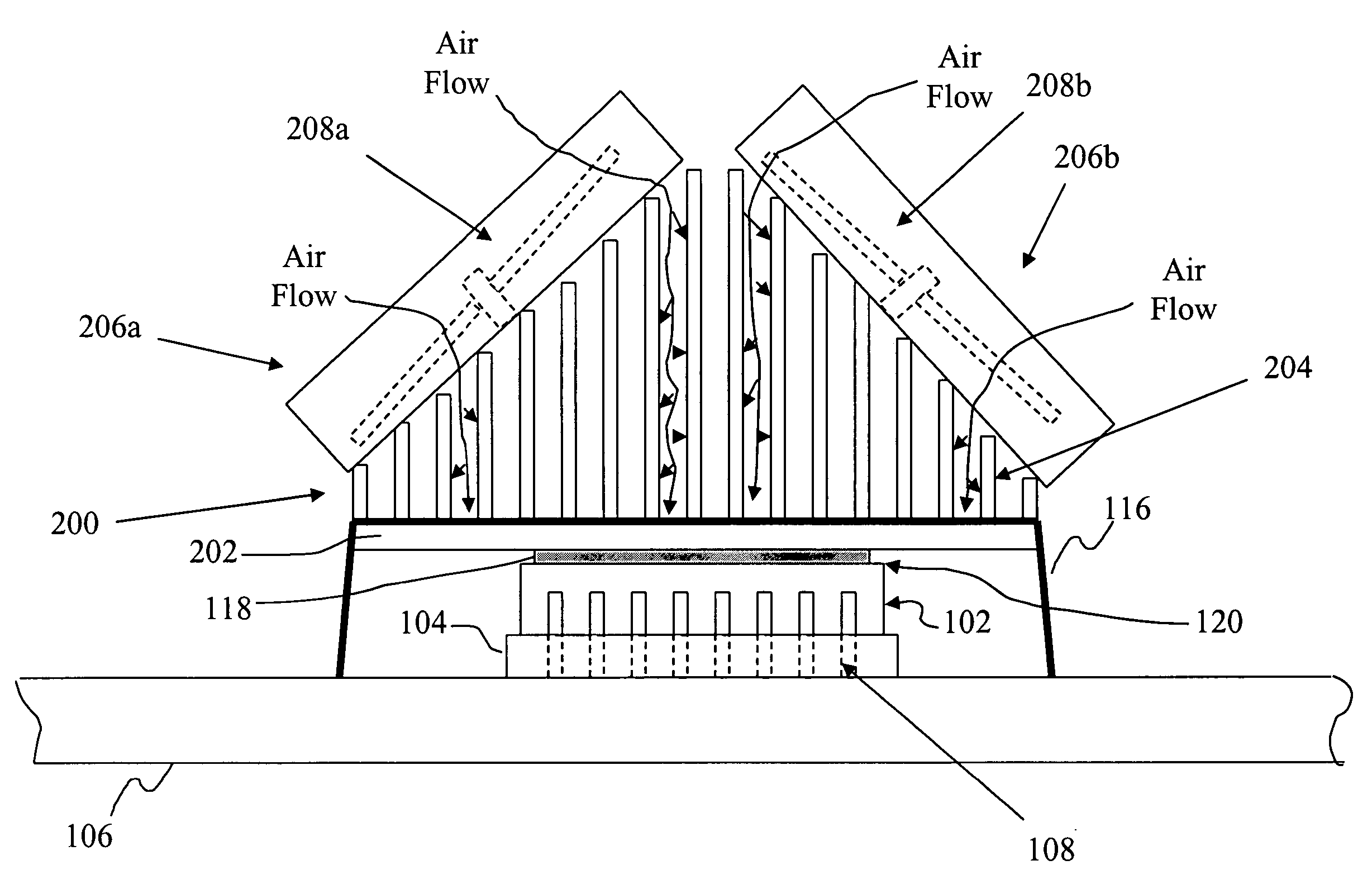
[0013] With reference now to FIG. 2, there is depicted a side view of a novel graduated heat sink 200. Graduated heat sink 200 has a base 202, to which multiple graduated fins 204 are mounted, preferably being mounted normal (perpendicular) to the top of base 202. Heat sink 200 is secured above and against processor 102 in any manner known to those skilled in the art of heat sinks, including the manner described above for FIG. 1a, and will not be reiterated here.

[0014] Note that the center of base 202 is oriented above processor 102 such that the graduated fins 204 of the greater length are oriented above the center of the top of processor 102, while the graduated fins 204 of the lesser length are oriented about the periphery of base 202, and thus are above or offset to the edges of the top of processor 102. This orientation is significant since it is the center of processor 102 that generates more heat than the periphery of processor 102. Thus, the graduated fins 204 having the gr...


PUM


Abstract

A heat sink having graduated lengths of fins, with the tallest fins being in the center of the heat sink to provide maximum heat removal from a mated integrated circuit (IC) chip. Dual fans impinge air against the fins, and particularly the tallest fins, to provide a highly efficient system for heat removal from the IC chip. By reducing the size of the lateral fins, additional space is made available for the dual fans. The use of the dual fans allows the fans to run at a lower speed that a single fan, thus reducing an overall fan acoustic level. Furthermore, the dual fans allow for a backup fan system if one of the fans should fail.

Description

BACKGROUND OF THE INVENTION [0001] 1. Technical Field [0002] The present invention relates in general to the field of electronics, and in particular to electronic chips that generate extraneous heat during normal operation. More particularly, the present invention relates to a method and system for conducting heat away from an integrated circuit, which still more particularly may be a microprocessor. [0003] 2. Description of the Related Art [0004] In a typical personal computer (PC), the main heat-generating component among the logic circuits is the processor, also referred to as the Central Processing Unit (CPU) or microprocessor (MP). As illustrated in FIG. 1a, a processor 102 is mounted in a socket 104, which is mounted on a (printed) circuit board 106 by mating pins 108 from the processor 102 into the socket 104. As processors continue to grow in performance, so does the heat generated by the processors. To remove heat from processor 102, a heat sink (HS) 110, having a HS base 1...

Claims


Application Information

Patent Timeline
IPC IPC(8): H05K7/20
CPCH01L23/467H01L2924/0002H01L2924/00
Inventor FOSTER, JIMMYJUNE, MICHAELMAKLEY, ALBERTMATTESON, JASON
Owner LENOVO GLOBAL TECH INT LTD
Why Eureka
Try Eureka