
Turntable having multiple-point touch function for a digital sound-signal device

Inactive Publication Date: 2012-05-01
HO CHIN CHEN
View PDF4 Cites 1 Cited by
  • Summary
  • Abstract
  • Description
  • Claims
  • Application Information

AI Technical Summary

Benefits of technology

[0006]The objective of this invention is to offer a turntable having multiple-point touch-function for a digital sound-signal device, able to output different sound signals when different locations of a touch-control turntable are touched, and sound broadcasting speed able to be lowered or retrieved by the manual force imposed on the turntable.

Problems solved by technology

At present, a CD player is operated to read a CD by laser light and the CD is only rotated clockwise perpetually at fixed lines and speeds in the course of broadcasting, thus impossible to create different sound effects; therefore, a DJ sill likes to perform by means of traditional record tray.
However, one traditional record can be cut thereon with only a few songs so a DJ has to carry a large box of records with him in order to carry out performance, taking a lot of exertion and causing much inconvenience.
However, a turntable with a single-point contact function can produce only one sound signal and further, when the turntable is touched by hand, music will be immediately stopped broadcasting, unable to simulate a traditional record tray because there is a record pad positioned between the record and the record tray; therefore, when the record tray is rotated and the record is slightly touched, a frictional force between the record and the record pad will be produced to lower the rotating speed of the record but not completely stop the record.
The conventional turntable with single-point contact mentioned above cannot store multiple sound signals, nor can it decide to lower or retrieve sound-signal broadcasting speeds by manual force imposed on the turntable.

Method used


Image

  • Turntable having multiple-point touch function for a digital sound-signal device
  • Turntable having multiple-point touch function for a digital sound-signal device
  • Turntable having multiple-point touch function for a digital sound-signal device

Examples


Embodiment Construction

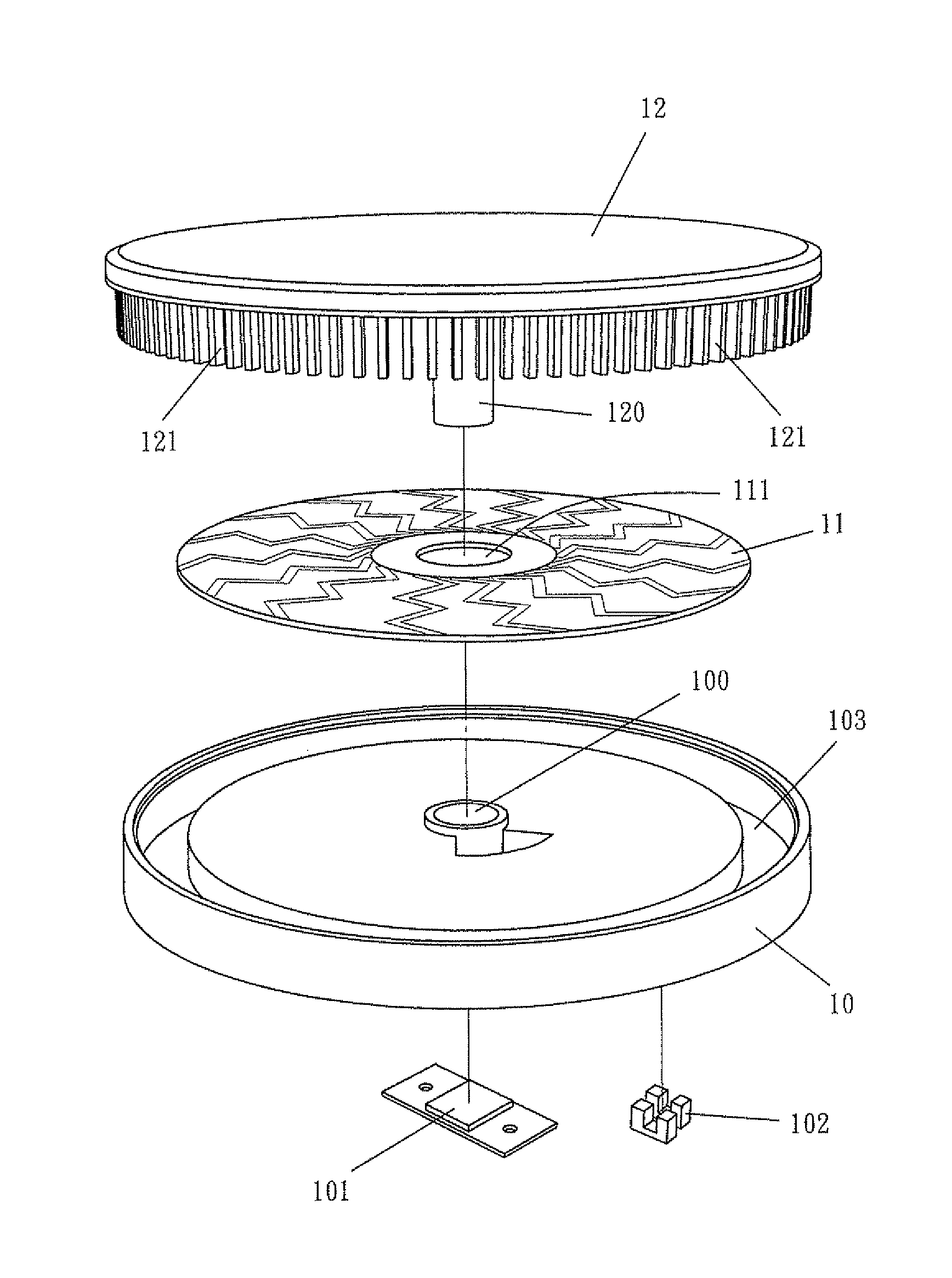
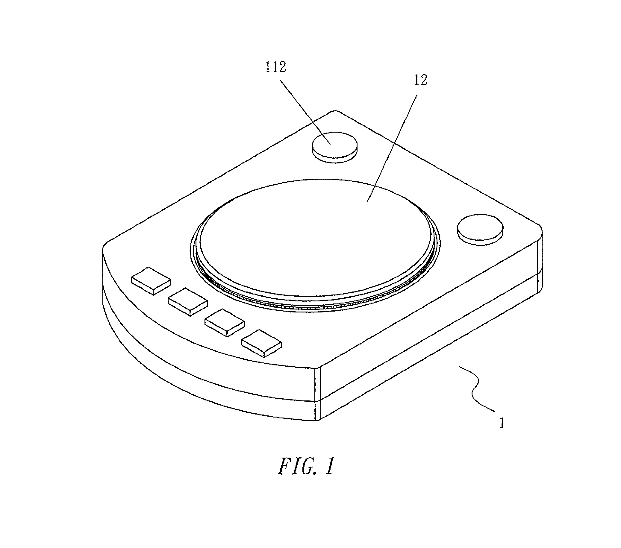
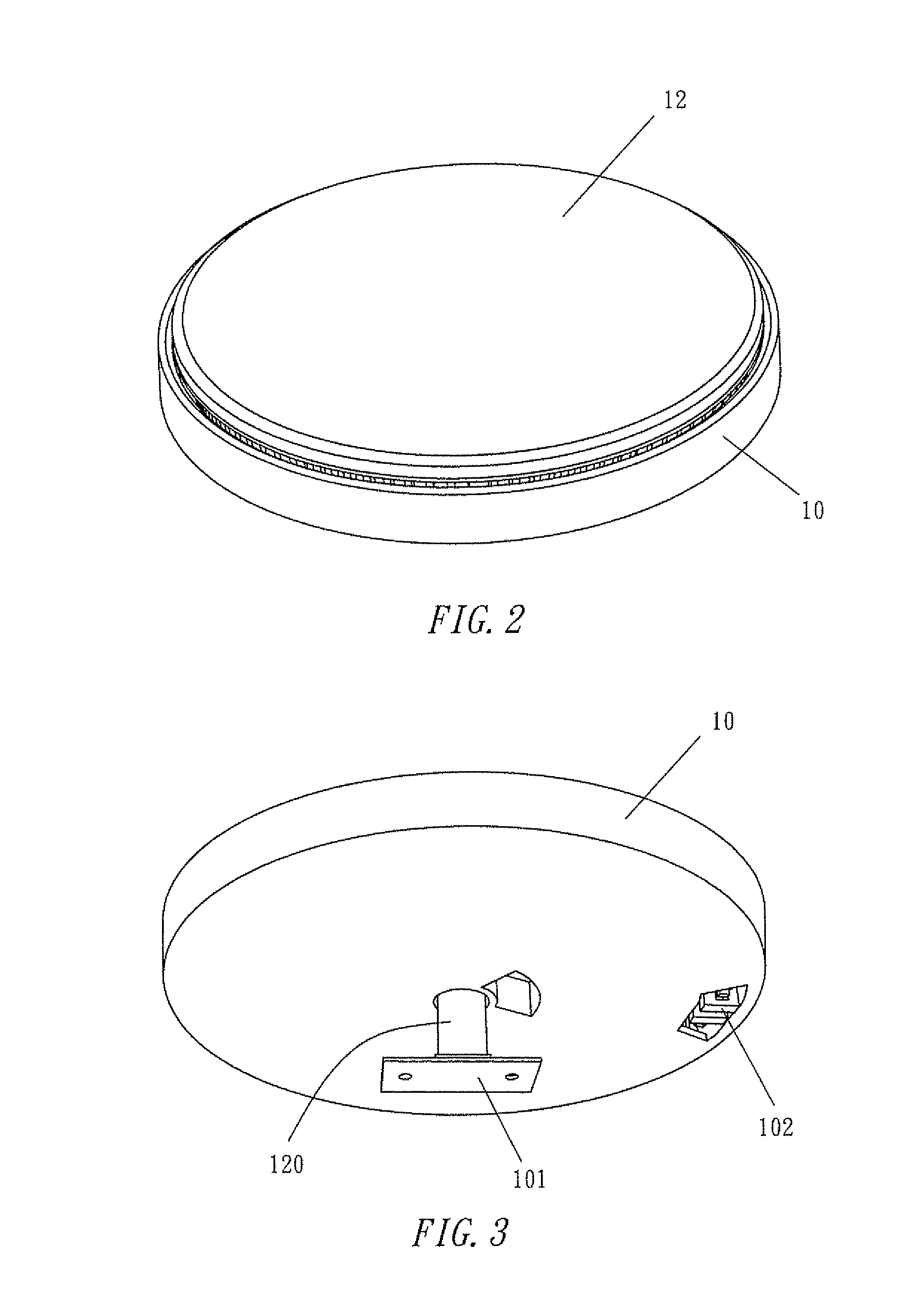
[0015]A preferred embodiment of a turntable having multiple-point touch function for a digital sound-signal device 1, touched and controlled by a DJ, in the present invention, as shown in FIGS. 1, 2 and 3, includes a base 10, a multiple-point touch-induction circuit board 11 and a touch-control turntable 12 as main components combined together.

[0016]The base 10 is bored with an insert hole 100 in the center and provided with a load sensor 101 under the insert hole 100 for controlling sound-signal broadcasting speeds. The base 10 further has its topside provided with a circular insert recess 103 around near an outer edge, with the insert hole 100 serving as a center of a circle, and a photo-sensor 102 fixed in the interior of the recess 103, as shown in FIGS. 3 and 4.

[0017]The multiple-point touch-induction circuit board 11 having multiple-point detecting function is fixedly stuck on the topside of the base 10. When a person's finger approaches a contact point that is to be induced b...


PUM


Abstract

A turntable having multiple-point touch function for a digital sound-signal device includes a base formed with a central insert hole having a lower side provided with a load sensor, with a photo-sensor installed at one inner end of the base. A multiple-point touch-induction circuit is fixed on the base, having different sensing regions and bored with a central through hole. A touch-control turntable assembled on the circuit board has a central post protruding downward to be inserted through both the through hole and the insert hole for combining the base, the circuit board and the turntable together, the combining post having its lower end touching the load sensor. The turntable has its outer end edge provided with lots of light-obstructing plates protruding downward for obstructing light with the photo-sensor. The touch-control turntable is preset with plural memory regions to be touched for outputting different sound effects.

Description

BACKGROUND OF THE INVENTION[0001]1. Field of the Invention[0002]This invention relates to a turntable having multiple-point touch function for a digital sound-signal device, particularly to one having a touch-control turntable divided into a plurality of memory regions. When a user's hand touches different locations on the touch-control turntable, the digital sound-signal device can output different sound signals or make sound effects of SCRATCH, and when the user slides the touch-control turntable upward and downward or leftward and rightward, action of skipping and picking out songs can be done. Further, the speed of sound signal broadcasting can be lowered or retrieved by the magnitude of force that a user touches the turntable.[0003]2. Description of the Prior Art[0004]Generally, on a sound-signal specialized occasion, a DJ likes to output different sound effects by scratching a record on a traditional record tray. (For instance, a DJ can quickly and precisely control a record t...

Claims


Application Information

Patent Timeline
IPC IPC(8): G11B20/10
CPCG11B19/02
Inventor HO, CHIN CHEN
Owner HO CHIN CHEN
Learn More