Hose Clamp Assembly

a technology of hose clamps and hoses, which is applied in the direction of cable arrangements between relatively moving parts, soil shifting machines/dredgers, constructions, etc., can solve the problems of time-consuming, difficult to work, and repeatable installation difficult and time-consuming

Active Publication Date: 2019-05-16
BLUE LEAF I P INC
View PDF1 Cites 11 Cited by
  • Summary
  • Abstract
  • Description
  • Claims
  • Application Information

AI Technical Summary

Benefits of technology

[0014]According to another aspect of the invention, the first plurality of semi-circular openings may align with the third plurality semi-circular openings when the first outer edge abuts the third outer edge in a first configuration. In the first configuration, a first hose is held between the first clamp block and the second clamp block. Alternatively, the second plurality of semi-circular openings may align with the fourth plurality of semi-circular openings when the second outer edge abuts the fourth outer edge in a second configuration. In the second configuration, a second hose is held between the first clamp block and the second clamp block. Additionally, the first hose may have a first diameter and the second hose may have a second diameter, where the first diameter is larger than the second diameter. The hose clamp assembly may additionally have a fifth plurality of semi-circular openings extending from the first outer edge to the second outer edge and a sixth plurality of semi-circular openings extending from the third outer edge toward the fourth outer edge. In the first configuration, the fifth plurality of semi-circular openings may align with the sixth plurality of semi-circular openings when the first outer edge abuts the third outer edge. Furthermore, the second clamp block may be substantially identical to the first clamp block.

Problems solved by technology

However, the lengths and bulk of the hoses, tubes, and the like of large and complex off-road agricultural vehicles make them difficult to work with, which can make repeatable installation difficult and time-consuming.

Method used


Image

  • Hose Clamp Assembly
  • Hose Clamp Assembly
  • Hose Clamp Assembly

Examples


Embodiment Construction

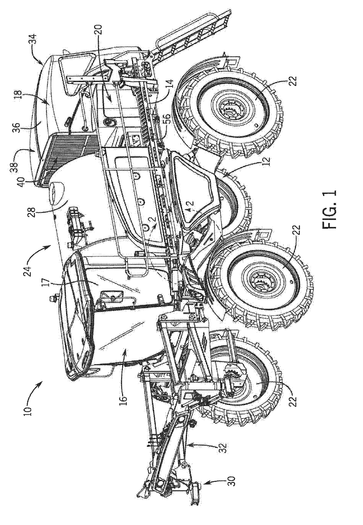
[0029]Referring now to the drawings and specifically to FIG. 1, aspects of the invention are shown for use with an agricultural machine which could be an agricultural sprayer. The agricultural sprayer is shown here as a self-propelled agricultural sprayer vehicle or self-propelled sprayer 10. Although sprayer 10 is shown as a front-mounted boom self-propelled sprayer, it is understood that self-propelled versions of sprayer 10 can have either front-mounted or rear-mounted booms, such as those available from CNH Industrial, including the Miller Nitro and Condor Series sprayers and. New Holland Guardian Series sprayers.

[0030]Still referring to FIG. 1, sprayer 10 includes a chassis 12 having a chassis frame 14 that supports various assemblies, systems, and components. These various assemblies, systems, and components can include an operator cab 16, an engine 18 and a hydraulic system 20. The hydraulic system 20 receives power from the engine 18 and includes at least one hydraulic pump ...


PUM


Abstract

A hose clamp assembly for use with an agricultural machine that help to route hoses or other elongate routed components about the agricultural machine. The hose clamp assembly may include a first clamp block having first and second outer walls, with at least a first set of openings formed in one of the first and second outer walls. Additionally, the first clamp block may further include a second set of openings formed into the other of the first and second outer walls. The first clamp block may be secured to the agricultural machine, to a mounting bracket, or to a lock plate. Additionally, the hose clamp assembly may have a second clamp block having third and fourth outer walls. The second clamp block may have a third set of openings formed therein, as well as a fourth set of openings. The clamp blocks may be mounted to one another.

Description

FIELD OF THE INVENTION[0001]The invention relates generally to agricultural product application equipment or agricultural machines such as self-propelled sprayers and, in particular, to a hose clamp assembly to secure a hose or hoses relative to the sprayer, with at least one clamp block configured to accommodate hoses of various diameters.BACKGROUND OF THE INVENTION[0002]High-clearance sprayers are getting larger and more complex to allow for increasing coverage in a single pass, which improves application efficiency. These high-clearance sprayers require numerous hoses, tubes, and the like for hydraulic systems, wet systems that include liquid product and rinse liquid dispensing capabilities, and other systems such as brake hand propel hoses. Many of the hoses, tubes, and the like have different diameters. Routing and securing such elongate routed components can be an important part of vehicle design in order to provide a neat appearance while offering protection for the hoses, tu...

Claims


Application Information

Patent Timeline
Patent Type & Authority Applications(United States)
IPC IPC(8): F16L3/22F16L3/10E02F9/22
CPCF16L3/222E02F9/2275F16L3/1091H02G11/00B05B15/16H02G3/30F16L3/2235B05B15/62H02G3/32
Inventor SCHWALBE, BLAINE A.TREINEN, KERRY J.MORETTI, STEPHEN
Owner BLUE LEAF I P INC
Why Eureka
Try Eureka