
Sump pump activation switch

a technology of pump activation switch and switch, which is applied in the direction of pump control, positive displacement liquid engine, non-positive displacement fluid engine, etc., can solve the problems of improper mounting of sensors, poor ground reference, and switch to malfunction

Inactive Publication Date: 2009-05-14
ABBOTT BRYAN L
View PDF3 Cites 17 Cited by
  • Summary
  • Abstract
  • Description
  • Claims
  • Application Information

AI Technical Summary

Benefits of technology

"The disclosed device is a replacement for a marine sump pump switch that is immersed in fluid such as water. The device uses an electronic circuit to constantly sample the fluid for an electronic property using a sensor that communicates with the fluid. The device employs a casing with two components that enhance performance of the internal electronic switch. The first component is a mounting member that is attached to the hose bib on the pump, ensuring proper placement in the fluid. The second component is a grounding component that is connected to the battery, providing a good ground reference for the sensor. The device is designed to be easily installed and can be used on a variety of boats and tanks. The technical effects of the invention include improved performance and reliability of the sump pump switch and casing, as well as increased user-friendliness and ease of installation."

Problems solved by technology

Water covering a metallic component will change the frequency sufficiently to flip the logic circuit to turn on power to the pump, however ungrounded tanks such as fiberglass tanks or those on fiberglass boats, and improperly mounted sensor components communicating with the fluid, will cause the switch to malfunction.
This problem with improperly mounted sensors and poor ground reference has been exacerbated in prior manufactured devices which have employed a casing wherein the two or more metal electronic monitor components communicating through the casing, have to be properly oriented in the fluid.
Users installing such devices frequently do not read the directions and install them incorrectly.
Most such devices employ screw apertures to mount the device in the tank and invite improper installation by installers who assume one or both metal components must be below water level.

Method used


Image

  • Sump pump activation switch
  • Sump pump activation switch
  • Sump pump activation switch

Examples


Embodiment Construction

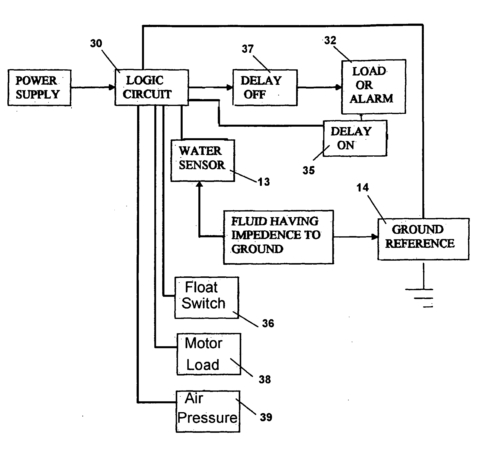
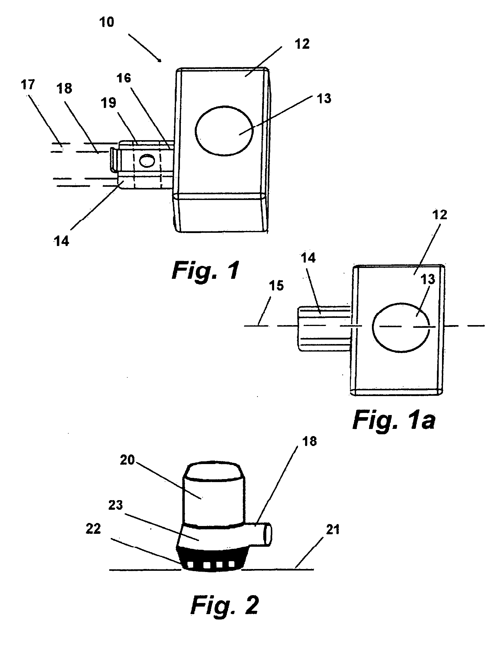
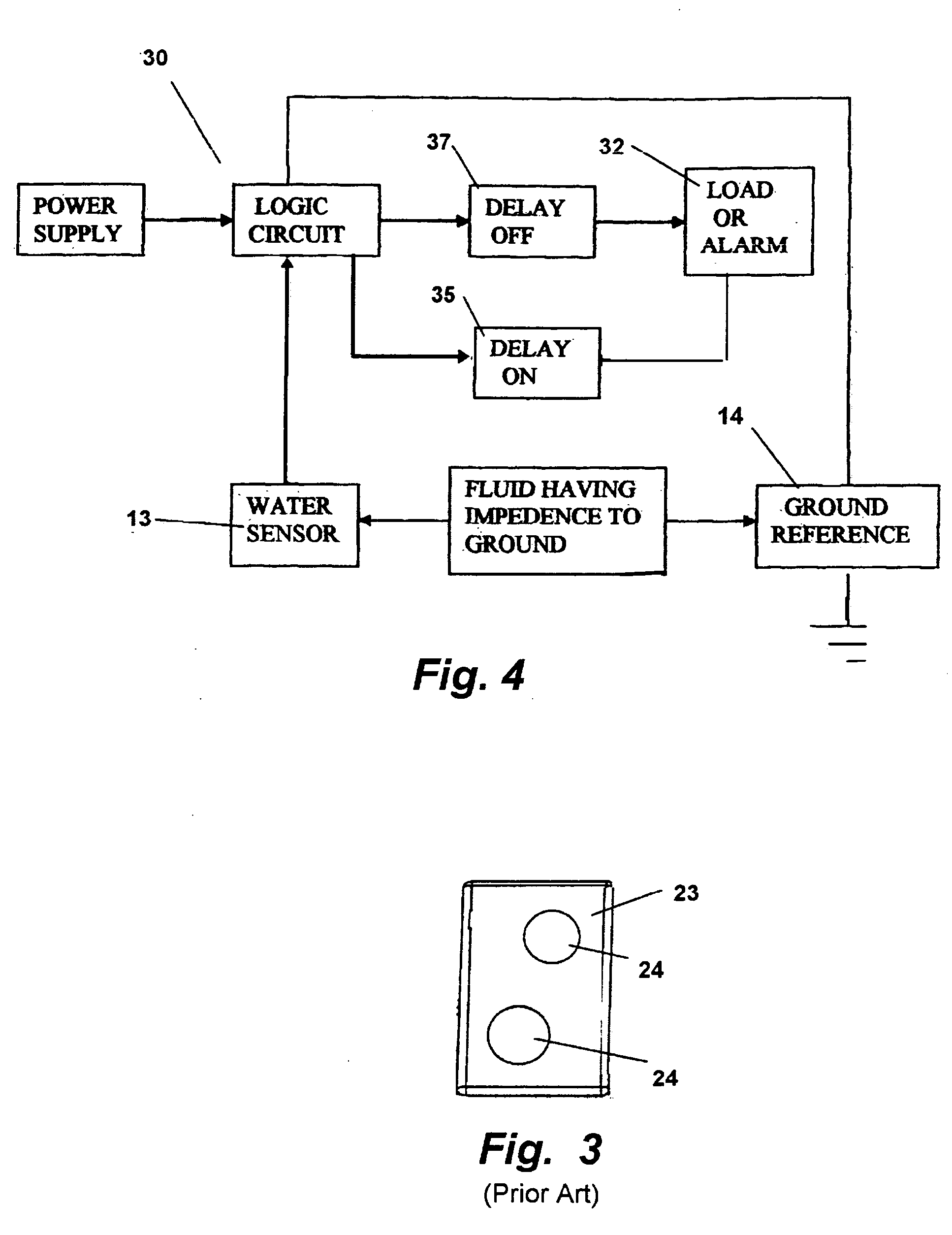
[0029]Referring now to the drawings in FIGS. 1-5, FIG. 1 shows a perspective view of the disclosed sump pump switch device 10 having a housing 12 having and extending grounded metal mounting member 14 which has a curve about its center axis or curved edge 16 portion. The electronic components for the impedance sensing device are engaged inside the housing 12 in a fashion that seals them from fluid in the tank. Wires (not shown) communicate to the circuit inside the housing 12 to provide electric energy to the circuit.

[0030]The mounting member 14 is connected inside the housing 12 to the ground wire or circuit providing electric power to the device 10 thereby providing the mounting member 14 a direct electrical link to the ground of the electrical system or battery. The curved shape of the mounting member 14 provides it with a means for cooperative surface engagement with the curved surface of a sump pump exhaust hose 17 which is engaged over a hose bib 18 and secured with a hose cla...


PUM


Abstract

A switching device for submersed sump pump. The switching device employs an internal logic circuit inside a housing having a metallic member extending therefrom for mounting. The member is adapted to engage with the curved surface of a hose and hose clamp engaged to the sump pump. The member is engaged to the electrical ground to communicate a reference ground to the fluid in the sump to allow an impedance sensor to discern the fluid level and cause the logic circuit to energize or de-energize the sump pump.

Description

[0001]This application claims priority from U.S. Provisional Patent Application Ser. No. 60 / 937,599 filed Jun. 27, 2007, and incorporated herein in its entirety by reference.FIELD OF THE INVENTION[0002]The disclosed device relates to fluid activated switches for electrical devices. More particularly, the disclosed device relates to a switch for a sump pump having a hose mount that imparts a ground reference to the water or fluid while concurrently insuring the user self-installs the device at a proper level in the water to ensure proper operation.BACKGROUND OF THE INVENTION[0003]Sump pumps are commonly employed on boats and ships to ensure that the bilge tanks do not overflow and are promptly and automatically emptied when needed. Another common function of a sump pump is to protect a basement from flooding.[0004]In such installations, the pump is conventionally activated when water or other fluid reaches a certain level in the sump tank or bilge. Once activated by a switch the pump...

Claims


Application Information

Patent Timeline
Patent Type & Authority Applications(United States)
IPC IPC(8): F04B49/02
CPCF04D15/0218
Inventor ABBOTT, BRYAN L.
Owner ABBOTT BRYAN L
Learn More