Image display system, and control apparatus for head-mounted display and operation method therefor

a display system and control apparatus technology, applied in the field of image display system, control apparatus for head-mounted display and operation method therefor, can solve the problems of delicate operation, time-consuming and laborious, and achieve the effect of quick and accurate operation

Active Publication Date: 2019-05-16
FUJIFILM CORP
View PDF0 Cites 27 Cited by
  • Summary
  • Abstract
  • Description
  • Claims
  • Application Information

AI Technical Summary

Benefits of technology

[0033]According to the present invention, switching between the rough adjustment mode in which the range of settable numerical values for the numerical value setting user interface, which is a virtual user interface, is the first range or / and the unit change width for a numerical value is the first change width, and the fine adjustment mode in which the range is the second range narrower than the first range or / and the unit change width is the second change width narrower than the first change width is performed in accordance with a gesture made by a user. Accordingly, it is possible to provide an image display system, and a control apparatus for a head-mounted display and an operation method therefor with which setting of a numerical value using a numerical value setting user interface, which is a virtual user interface, can be quickly and accurately performed.

Problems solved by technology

However, it is often the case that the numerical value indication part repeatedly moves past a position corresponding to a numerical value to be set several times, so that numerical value setting takes time.
Therefore, to set a numerical value quickly and accurately, a delicate operation needs to be performed.
Accordingly, a delicate operation can be relatively easily performed.
Accordingly, in the operation for the virtual UI, the user has difficulty in having an operational feel in terms of the sense of touch, and therefore, the user relatively has difficulty in performing a delicate operation.
Here, it is relatively difficult to perform a delicate operation for the virtual UI as described above, and therefore, there is a possibility that numerical value setting takes more time than in the case of the non-virtual UI.

Method used


Image

  • Image display system, and control apparatus for head-mounted display and operation method therefor
  • Image display system, and control apparatus for head-mounted display and operation method therefor
  • Image display system, and control apparatus for head-mounted display and operation method therefor

Examples


first embodiment

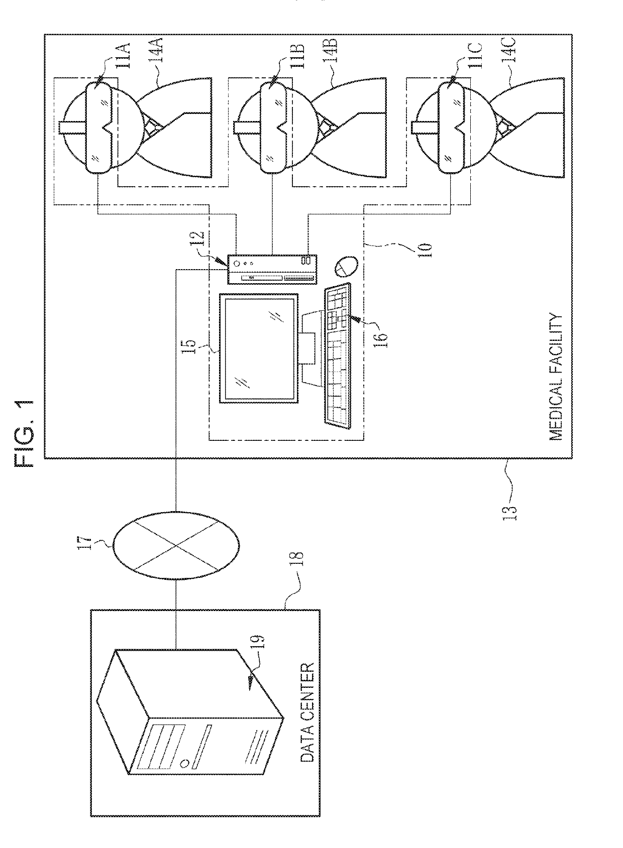
[0076]In FIG. 1, an image display system 10 includes HMDs 11A, 11B, and 11C and a control apparatus 12 and is placed in a medical facility 13. The HMD 11A is worn on the head of a user 14A, the HMD 11B is worn on the head of a user 14B, and the HMD 11C is worn on the head of a user 14C. The users 14A to 14C are medical staff members including doctors and nurses who belong to the medical facility 13. Note that the head is a part of the human body that is located above the neck of the human body in a standing position state, and is a part that includes the face and so on. Hereinafter, the HMDs 11A to 11C may be collectively referred to as HMDs 11 and the users 14A to 14C may be collectively referred to as users 14 in a case where these need not be specifically distinguished from each other.

[0077]The control apparatus 12 is, for example, a desktop personal computer and has a display 15 and an input device 16 constituted by a keyboard and a mouse. The display 15 displays a screen that i...

second embodiment

[0165]In the first embodiment described above, the description has been given under the assumption that the display position of the slide bar 45 in the virtual space VS is fixed; however, the display position in the real space RS may be fixed similarly to the 3D image 40.

[0166]FIG. 25 illustrates a state where the marker 39 is put on a wall 80, the slide bar 45 is made to appear on the wall 80, and the user 14 makes a gesture using the hand 38 for the slide bar 45 displayed on the wall 80. Accordingly, the slide bar 45 can be displayed at a place desirable to the user 14, and the slide bar 45 can be displayed at a remote position, such as the wall 80, that is physically out of reach of the hand 38 of the user 14 in the augmented reality space ARS.

[0167]The state where the hand 38 does not reach the slide bar 45 is intentionally created, which produces an effect in which a disadvantage of the virtual UI, that is, no sensation of actual touching, is offset. For operating the slide bar...

third embodiment

[0170]In the first embodiment described above, the numerical value is changed in accordance with the movement amount of the hand 38. Therefore, depending on the difference between the currently set numerical value and a numerical value that the user 14 wants to set or the setting of the change width of a numerical value relative to the unit movement amount of the hand 38, the user 14 may need to move the hand 38 relatively widely. In this case, if the user 14 is in a situation where the user 14 is unable to move the hand 38 widely, numerical value setting may become difficult. Above all, the user 14 may be tired when the user 14 moves the hand 38 widely. Accordingly, in a third embodiment illustrated in FIG. 26 and FIG. 27, numerical value setting can be performed with a small movement amount of the hand 38.

[0171]In the third embodiment, a captured image from the camera 29 is substantially equally divided into three areas 85A, 85B, and 85C vertically, as illustrated in FIG. 26. In a...


PUM


Abstract

A second detection unit detects a second gesture for switching between a rough adjustment mode in which the range of settable numerical values for a slide bar is a first range or/and the unit change width for a numerical value is a first change width and a fine adjustment mode in which the range is a second range narrower than the first range or/and the unit change width is a second change width narrower than the first change width. A mode switching unit switches between the rough adjustment mode and the fine adjustment mode in accordance with the second gesture. A display control unit causes a rough adjustment slide bar and a fine adjustment slide bar to be selectively displayed on an HMD.

Description

CROSS-REFERENCE TO RELATED APPLICATIONS[0001]This application is a Continuation of PCT International Application No. PCT / JP2017 / 022488 filed on 19 Jun. 2017, which claims priority under 35 U.S.C. § 119(a) to Japanese Patent Application No. 2016-137813 filed on 12 Jul. 2016. The above application is hereby expressly incorporated by reference, in its entirety, into the present application.BACKGROUND OF THE INVENTION1. Field of the Invention[0002]The present invention relates to an image display system, and a control apparatus for a head-mounted display and an operation method therefor.2. Description of the Related Art[0003]A technique is known in which a virtual image formed by using computer graphics is displayed on a head-mounted display (hereinafter referred to as “HMD”) that is worn on the head of a user to allow the user to recognize an augmented reality space obtained by merging the real space with a virtual space. For example, JP2015-119373A (corresponding to US2016 / 0320863A1) ...

Claims


Application Information

Patent Timeline
Patent Type & Authority Applications(United States)
IPC IPC(8): G06F3/01G06T19/00
CPCG06F3/011G06F3/017G06T19/006G06F3/04815G06F3/04847
Inventor IKUTA, MAYUKOOKABE, YUKIIDA, NORIAKI
Owner FUJIFILM CORP
Why Eureka
Try Eureka