Artificial shuttlecock feather and shuttlecock

a technology of artificial feathers and shuttlecocks, which is applied in the field of artificial feather shuttlecocks and shuttlecocks, can solve the problems of difficult to achieve flight performance similar to that of natural feather shuttlecocks, and the feathers are not able to move independently of each other in such artificial feather shuttlecocks, so as to achieve the effect of improving flight performan

Active Publication Date: 2019-05-23
YONEX CO LTD +1
View PDF9 Cites 5 Cited by
  • Summary
  • Abstract
  • Description
  • Claims
  • Application Information

AI Technical Summary

Benefits of technology

[0016]The artificial shuttlecock feather of the in

Problems solved by technology

Although artificial feather shuttlecocks provided with feathers made from resin integrally molded into a ring shape are well known, the feathers are not able to move individually independently of each

Method used


Image

  • Artificial shuttlecock feather and shuttlecock
  • Artificial shuttlecock feather and shuttlecock
  • Artificial shuttlecock feather and shuttlecock

Examples


embodiments

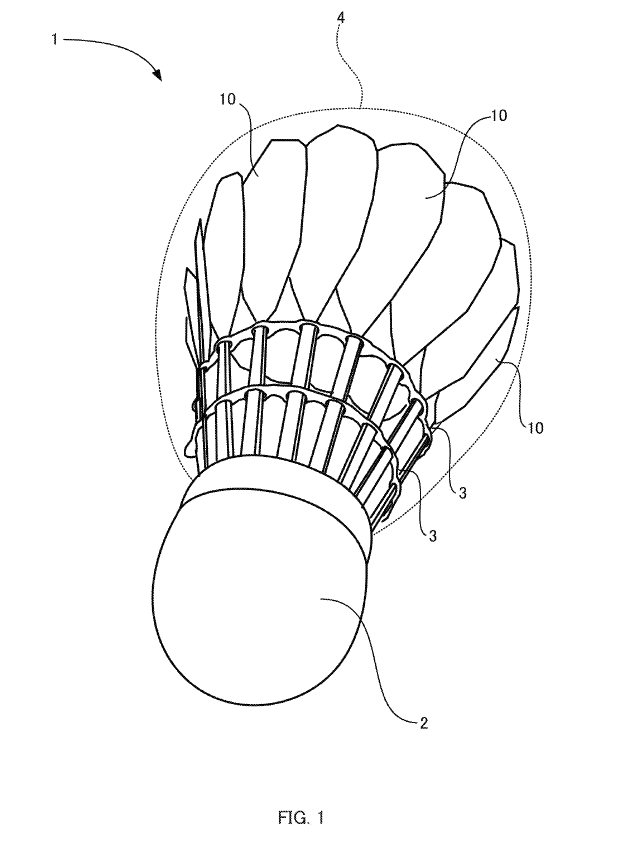
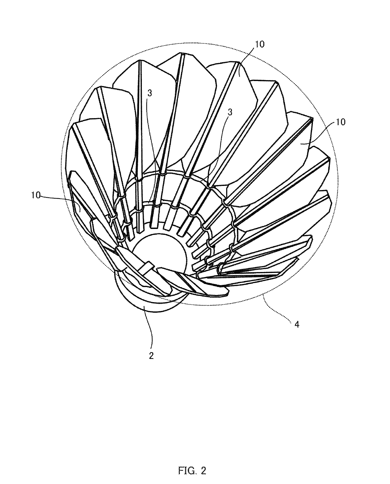
[0041]FIG. 1 and FIG. 2 are external views to explain the basic structure of an artificial feather shuttlecock 1 provided with artificial feathers 10. FIG. 1 is a perspective view illustrating the artificial feather shuttlecock 1, as viewed from a base 2 side. FIG. 2 is a perspective view illustrating the artificial feather shuttlecock 1, as viewed from the artificial feather 10 side.

[0042]The artificial feather shuttlecock 1 includes a base 2, plural of the artificial feathers 10 modelled on natural feathers, and cord shaped members 3 for fixing the artificial feathers 10 together. The base 2 is configured by, for example, covering a cork mounting block with thin leather. The shape of the base 2 is a hemispherical shape having a diameter of from 25 mm to 28 mm and including a flat face. Basal portions (base ends: corresponds to one end) of the plural artificial feathers 10 are embedded in a circular ring shape around the circumference of the flat face. The plural artificial feather...

modified examples

[0080]FIG. 9 is a diagram illustrating an artificial feather 10 of a first modified example, as viewed from the back side.

[0081]Plural holes 124 are provided in a vane section 12 of the artificial feather 10 of the first modified example. Opening widths (top-to-bottom direction lengths) of the holes 124 are greater than the opening widths of the holes 122 of the above embodiment, and the separation between the adjacent holes 124 is also greater than the separation between the holes 122 in the above embodiment. Namely, the number of the holes 124 in the first modified example is fewer than in the above embodiment. Similarly to in the above embodiment, the holes 124 are provided in a second region 12B to the upper side (distal end side) of the position P2.

[0082]FIG. 10 is a diagram illustrating an artificial feather 10 of a second modified example, as viewed from the back side.

[0083]Plural holes 126 are provided in a vane section 12 of the artificial feather 10 of the second modified ...


PUM


Abstract

An artificial shuttlecock feather that is to be implanted in a circular ring shape into a base of a shuttlecock, the artificial shuttlecock feather includes: a vane section; and a rachis section having one end in an axial direction of the rachis section fixed to the base and supporting the vane section provided to another end side of the rachis section, a hole being formed in the vane section so as to penetrate the vane section, and a porosity of a first region of the vane section being lower than a porosity of a second region of the vane section, the first region spanning from an edge on the one end side in the axial direction to a predetermined position further toward the one end side than a center of vane section in the axial direction, the second region spanning from the predetermined position to an edge on the other end side in the axial direction.

Description

RELATED APPLICATION[0001]This application is the U.S. National Phase under 35 U.S.C. § 371 of International Application No. PCT / JP2017 / 016888, filed Apr. 28, 2017, which in turn claims the benefit of Japanese Application No. 2016-093666, filed May 9, 2016, the contents of which are incorporated herein by reference in their entirety.TECHNICAL FIELD[0002]The present invention relates to an artificial shuttlecock feather and a shuttlecock.BACKGROUND ART[0003]Badminton shuttlecocks include those that employ feathers (natural feathers) of waterfowl for their feathers (natural feather shuttlecocks), and those that employ artificial feathers synthetically manufactured from a nylon resin or the like therefor (artificial feather shuttlecocks).[0004]As is widely known, natural feather shuttlecocks have a structure using 16 or so natural feathers from a goose, duck, or the like, with a base end of the rachis of each feather implanted into a hemispherical mounting block (base) configured from l...

Claims


Application Information

Patent Timeline
IPC IPC(8): A63B67/19
CPCA63B67/19A63B2102/04A63B67/187
Inventor MATSUSHIMA, YUSUKESAKAGUCHI, TAKUMIKONISHI, YASUFUMI
Owner YONEX CO LTD
Why Eureka
Try Eureka