Economical plastic tooling cores for mold and die sets

a tooling core and plastic technology, applied in the field of plastic tooling industry, can solve the problems of uneconomical unfavorable use of similar grades in the core side of the tooling set, and the inability of the core side of the steel to take as much polish as the cavity sid

Active Publication Date: 2019-05-23
A FINKI & SONS
View PDF4 Cites 0 Cited by
  • Summary
  • Abstract
  • Description
  • Claims
  • Application Information

AI Technical Summary

Benefits of technology

This patent is about a set of plastic injection tools that have a core side and a cavity side. The core side has a specific composition that includes certain amounts of carbon, manganese, silicon, chromium, molybdenum, aluminum, phosphorus, sulfur, iron, and impurities. The technical effect of this composition is that the tooling can be used to efficiently inject plastic during the molding process.

Problems solved by technology

However, this and similar grades are uneconomical for use in the core side of tooling sets in the sense that the working attributes of such steels substantially exceed the attributes needed for the core side of tooling sets.
Thus, to the part manufacturer in today's highly cost conscious environment, using the above grade for the core side of a tooling set represents an unnecessary cost over a lower cost, yet sufficiently effective alloy.
However, the steel of which the core side is made need not be capable of taking as high a polish as does the cavity side since the core side is not seen.
Above this thickness, this composition may not maintain expected mechanical properties in depth.
Specifically, at thicknesses larger than 20″, this steel exhibits too much hardness drop at parting lines.

Method used


Image

  • Economical plastic tooling cores for mold and die sets
  • Economical plastic tooling cores for mold and die sets

Examples


Embodiment Construction

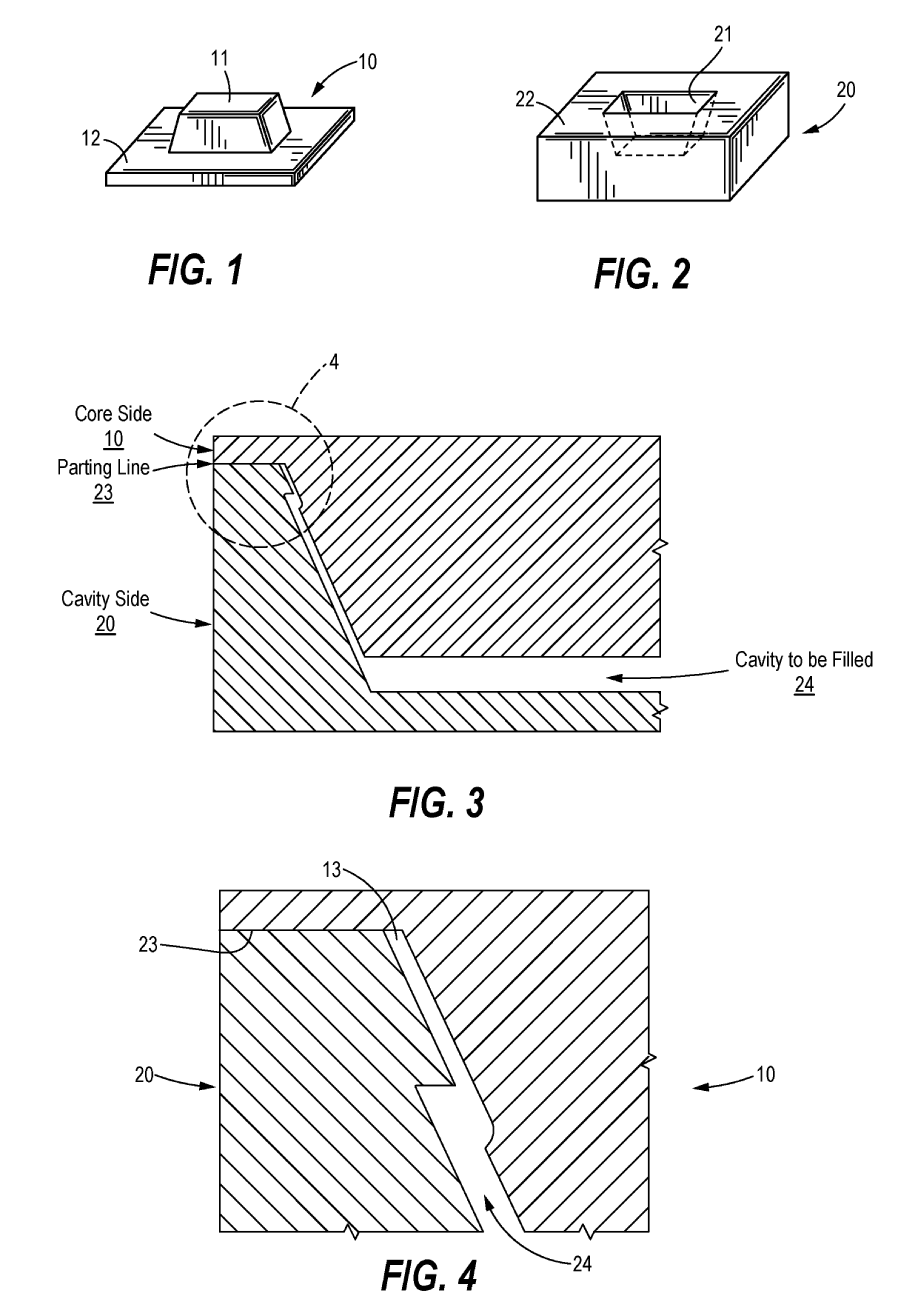
[0017]Referring first to FIG. 1, the core side of a plastic tooling set is indicated generally at 10, the core at 11 and the parting line plane at 12.

[0018]Referring next to FIG. 2, the cavity side of a plastic tooling set is indicated generally at 20, the cavity at 21 and the parting line plane at 22. It will be understood that when the core side 10 and the cavity side 20 are in molding engagement the parting line planes 12 and 22 will be in abutting engagement to form a parting line 23 (see FIG. 3), and the core side 11 will be received in the cavity 21.

[0019]Since the dimensions of the core 11 are slightly smaller than the dimensions of the cavity 21, a part will be formed in the space 24 between the core and the cavity (see FIG. 4). The two halves 10 and 20 will of course be held in fixed positions when closed by suitable means well known in the industry, not shown.

[0020]Referring now specifically to FIG. 4, it will be seen that the parting line 23 forms a clear line of demarcat...


PUM

PropertyMeasurementUnit
Temperatureaaaaaaaaaa
Angleaaaaaaaaaa

Abstract

A core side of a plastic injection molding tooling set for use in conjunction with a cavity side of the tooling set is disclosed. The core side may have the following composition in percent by weight: 0.25-0.55% carbon, 0.70-1.50% manganese, a maximum of 0.80% silicon, 1.40-2.00% chromium, 0.10-0.55% molybdenum, a maximum of 0.040% aluminum, a maximum of 0.025% phosphorous, a maximum of 0.20% sulfur, a balance of iron, and incidental impurities.

Description

CROSS-REFERENCE TO RELATED APPLICATION[0001]This application is a continuation-in-part pursuant to 35 U.S.C. § 120 of U.S. patent application Ser. No. 14 / 998,669 filed Feb. 1, 2016.FIELD OF THE DISCLOSURE[0002]This invention addresses problems in the plastic tooling industry pertaining to providing blemish free surfaces on mold and die components which are in molding contact with parts which are visible to the ultimate user. This invention also addresses the continuing problem of providing mold and die materials of differing alloy compositions for the core and cavity halves for a set of plastic tooling which yield high quality final products at a very economical cost.BACKGROUND OF THE DISCLOSURE[0003]It has been discovered that the two halves which make up a set of plastic tooling molds or dies must have different compositions and operating characteristics to produce high quality parts at a low cost in material cross sections of about twenty inches and higher. Specifically, the cavi...

Claims


Application Information

Patent Timeline
IPC IPC(8): B29C45/37C21D9/00
CPCB29C45/37C21D9/0068B29C33/3842B29K2905/00C21D6/002C21D6/005C21D6/008C22C38/22C22C38/06C22C38/04C22C38/02C22C38/12C21D2211/009C21D2211/002B29C33/38
Inventor LAPIERRE-BOIRE, LOUIS-PHILIPPE
Owner A FINKI & SONS
Why Eureka
Try Eureka