

Optical wide angle lens
- Summary
- Abstract
- Description
- Claims
- Application Information
AI Technical Summary
Benefits of technology
Problems solved by technology
Method used
Image

Examples
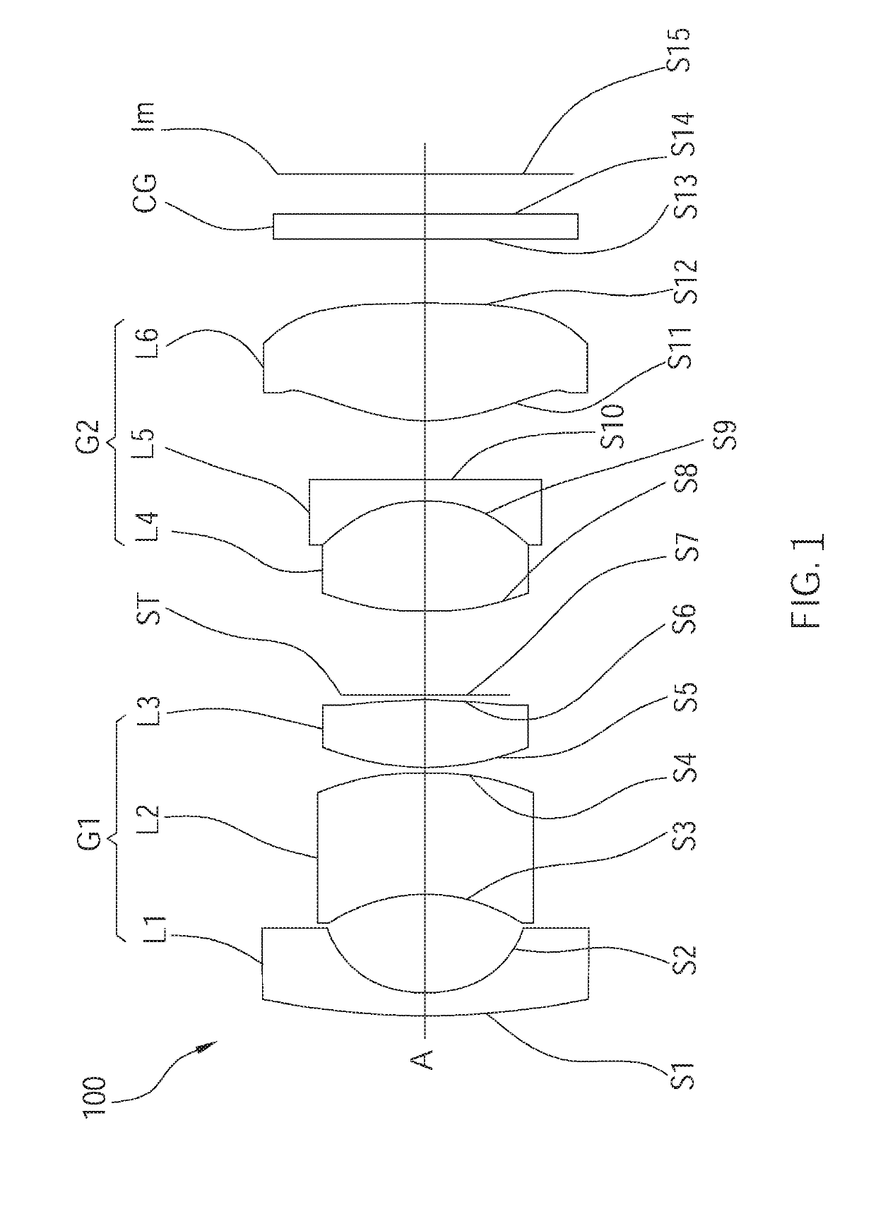
first embodiment
[0037]Said wide angle optical lens assembly 100 of the first embodiment further satisfies the following condition: 2.0≤|F1 / EFL|≤3.65; 2.6≤|F2 / EFL|≤3.45. Preferably, the wide angle optical lens assembly 100 satisfies the following condition: 2.2≤|F1 / EFL|≤3.0; 2.8≤|F2 / EFL|≤3.15; where EFL is an effective focal length of the wide angle optical lens assembly 100, F1 is the effective focal length of the first lens groupfirst lens group G1, F2 is the effective focal length of the second lens group G2. With the aforementioned design, the wide angle optical lens assembly 100 could have a wide angle of view, could be made with a small size, and could be lightweight, of which the total length is short.
[0038]Preferably, said wide angle optical lens assembly 100 of the first embodiment further satisfies the following condition: Nd4≤1.5; Vd4>70; Nd5>1.7; Vd5≤35; where Nd4 is a refractive index of the fourth lens L4, Vd4 is a dispersion coefficient of the fourth lens L4; Nd5 is a refractive index...
second embodiment
[0048]Said wide angle optical lens assembly 200 of the second embodiment further satisfies the following condition: 2.0≤|F1 / EFL|≤3.65; 2.6≤|F2 / EFL|≤3.45. With the aforementioned design, said wide angle optical lens assembly 200 could have a wide angle of view, could be made with a small size, and could be lightweight, of which the total length is short. Preferably, said wide angle optical lens assembly 200 further satisfies the following condition: Nd470; Nd5>1.7; and Vd54, Vd4 is a dispersion coefficient of the fourth lens L4; Nd5 is a refractive index of the fifth lens L5, Vd5 is a dispersion coefficient of the fifth lens L5. With the aforementioned design regarding the refractive indexes Nd4, Nd5 and the dispersion coefficients Vd4, Vd5 of the fourth lens L4 and the fifth lens L5, the longitudinal chromatic aberration of the wide angle optical lens assembly 200 could be further minimized, providing a better performance balance.
[0049]The parameters of the lenses of the wide angle ...
third embodiment
[0059]Said wide angle optical lens assembly 300 of the third embodiment further satisfies the following condition: 2.0≤|F1 / EFL|≤3.65; 2.6≤|F2 / EFL|≤3.45. With the aforementioned design, said wide angle optical lens assembly 300 could have a wide angle of view, could be made with a small size, and could be lightweight, of which the total length is short. Preferably, said wide angle optical lens assembly 300 further satisfies the following condition: Nd470; Nd5>1.7; and Vd54, Vd4 is a dispersion coefficient of the fourth lens L4; Nd5 is a refractive index of the fifth lens L5, Vd5 is a dispersion coefficient of the fifth lens L5. With the aforementioned design regarding the refractive indexes Nd4, Nd5 and the dispersion coefficients Vd4, Vd5 of the fourth lens L4 and the fifth lens L5, the longitudinal chromatic aberration of the wide angle optical lens assembly 300 could be further minimized, providing a better performance balance.
[0060]The parameters of the lenses of the wide angle o...
PUM
 Abstract
Description
Claims
Application Information