Power amplifier circuit

Active Publication Date: 2020-10-29
MURATA MFG CO LTD
View PDF0 Cites 0 Cited by
  • Summary
  • Abstract
  • Description
  • Claims
  • Application Information

AI Technical Summary

Benefits of technology

[0009]In this configuration, power supply voltages are supplied from different power supply circuits to the former amplifier and the latter amplifier. Accordingly, the power supply voltage may be controlled appropriately for the former amplifier and the latter amplifie

Problems solved by technology

In the case of performing power amplification using envelope tracking, if the power supply voltage is changed in accordance with the phase of an input signal supplied to a drive stage, due to a delay in signal propagation from the drive stage to a power stage, the phase of the input signal becomes out of phase with the phase of the power supply voltage at the power stage, which may deteriorate the distortion characteristics.
Along with transition to the fifth-generation mobile communication system, the circuit configuration of a front-end portion of a mobile communication terminal appar

Method used


Image

  • Power amplifier circuit
  • Power amplifier circuit
  • Power amplifier circuit

Examples


first embodiment

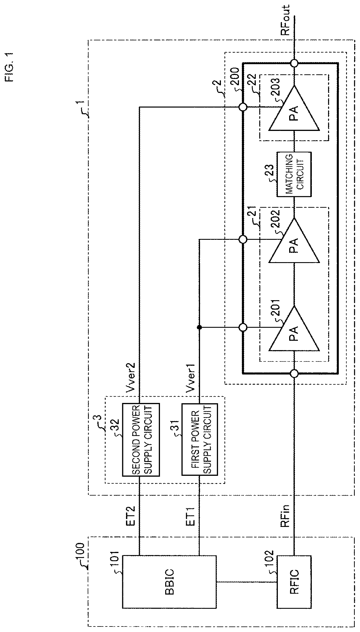
[0026]FIG. 1 is a diagram illustrating the configuration of a power amplifier circuit according to the first embodiment. A power amplifier circuit 1 according to the first embodiment is mounted on, for example, a wireless communication terminal that supports radio frequency (RF) communication using Sub 6 of the fifth-generation mobile communication system or the 5 GHz frequency band of Wi-Fi.

[0027]The power amplifier circuit 1 amplifies an RF input signal RFin input from a radio-frequency integrated circuit (RFIC) 102 of a controller 100, and outputs an RF output signal RFout. As illustrated in FIG. 1, the power amplifier circuit 1 according to the first embodiment includes an amplifier (first amplifier or first amplifier unit) 2 and a power supply circuit 3.

[0028]In the amplifier (first amplifier) 2, a former amplifier 21 and a latter amplifier 22 are connected in series with a matching circuit 23 interposed therebetween. The former amplifier 21 includes power amplifiers (PAs) 201 ...

second embodiment

[0068]FIG. 5 is a diagram illustrating the configuration of a power amplifier circuit according to a second embodiment. FIG. 6 is a diagram illustrating the configuration of a power amplifier circuit according to a modification of the second embodiment. The power amplifier circuit may have the configuration illustrated in FIG. 5 or the configuration illustrated in FIG. 6 depending on the gain distribution of the power amplifiers (PAs) 201, 202, and 203. Note that the same elements as those of the first embodiment are given the same reference symbols, and descriptions thereof are omitted.

[0069]In a power amplifier circuit 1b of the second embodiment and a power amplifier circuit 1c of the modification of the second embodiment, a matching circuit 24 provided between the former amplifiers 21 and 21a and the latter amplifiers 22 and 22a of amplifiers (first amplifiers) 2b and 2c includes a band-pass filter (BPF). The matching circuit 24 is included in power amplifier modules (PAMs) 200b...

third embodiment

[0072]In a third embodiment, the configuration including a plurality of amplifiers and realizing multi-band and broadband communication will be discussed. FIG. 7 is a diagram illustrating a first example of the schematic configuration of a power amplifier circuit according to a third embodiment. FIG. 8 is a diagram illustrating a second example of the schematic configuration of the power amplifier circuit according to the third embodiment. FIG. 9 is a diagram illustrating a third example of the schematic configuration of the power amplifier circuit according to the third embodiment. FIG. 10 is a diagram illustrating a fourth example of the schematic configuration of the power amplifier circuit according to the third embodiment. FIG. 11 is a diagram illustrating a fifth example of the schematic configuration of the power amplifier circuit according to the third embodiment. FIG. 12 is a diagram illustrating a sixth example of the schematic configuration of the power amplifier circuit ...


PUM


Abstract

A power amplifier circuit includes a first amplifier including two amplifiers connected in series with a matching circuit interposed therebetween, a first power supply circuit that supplies a first power supply voltage to a former amplifier of the first amplifier, and a second power supply circuit that supplies a second power supply voltage to a latter amplifier of the first amplifier.

Description

[0001]This application claims priority from Japanese Patent Application No. 2019-083359 filed on Apr. 24, 2019. The content of this application is incorporated herein by reference in its entirety.BACKGROUND[0002]The present disclosure relates to a power amplifier circuit.[0003]Examples of technology for increasing the efficiency of a power amplifier circuit mounted on a wireless communication terminal include envelope tracking (ET), which improves power efficiency by controlling the power supply voltage of a power amplifier according to the amplitude level of an input signal, and average power tracking (APT), which improves power efficiency by controlling the power supply voltage of a power amplifier according to the average output power. In general, envelope tracking achieves greater power efficiency than average power tracking when the output voltage of the power amplifier is great, and average power tracking achieves greater power efficiency than envelope tracking when the output...

Claims


Application Information

Patent Timeline
IPC IPC(8): H03F1/02H03F1/56H03F3/21
CPCH03F2200/222H03F3/211H03F2200/387H03F1/56H03F1/0288H03F1/32H03F1/02H03F3/68H03F3/20H03F1/0222H03F2200/451H03F3/195H03F2200/516
Inventor TAKENAKA, KIICHIRO
Owner MURATA MFG CO LTD
Why Eureka
Try Eureka