

Optical imaging lens
- Summary
- Abstract
- Description
- Claims
- Application Information
AI Technical Summary
Benefits of technology
Problems solved by technology
Method used
Image

Examples
first embodiment
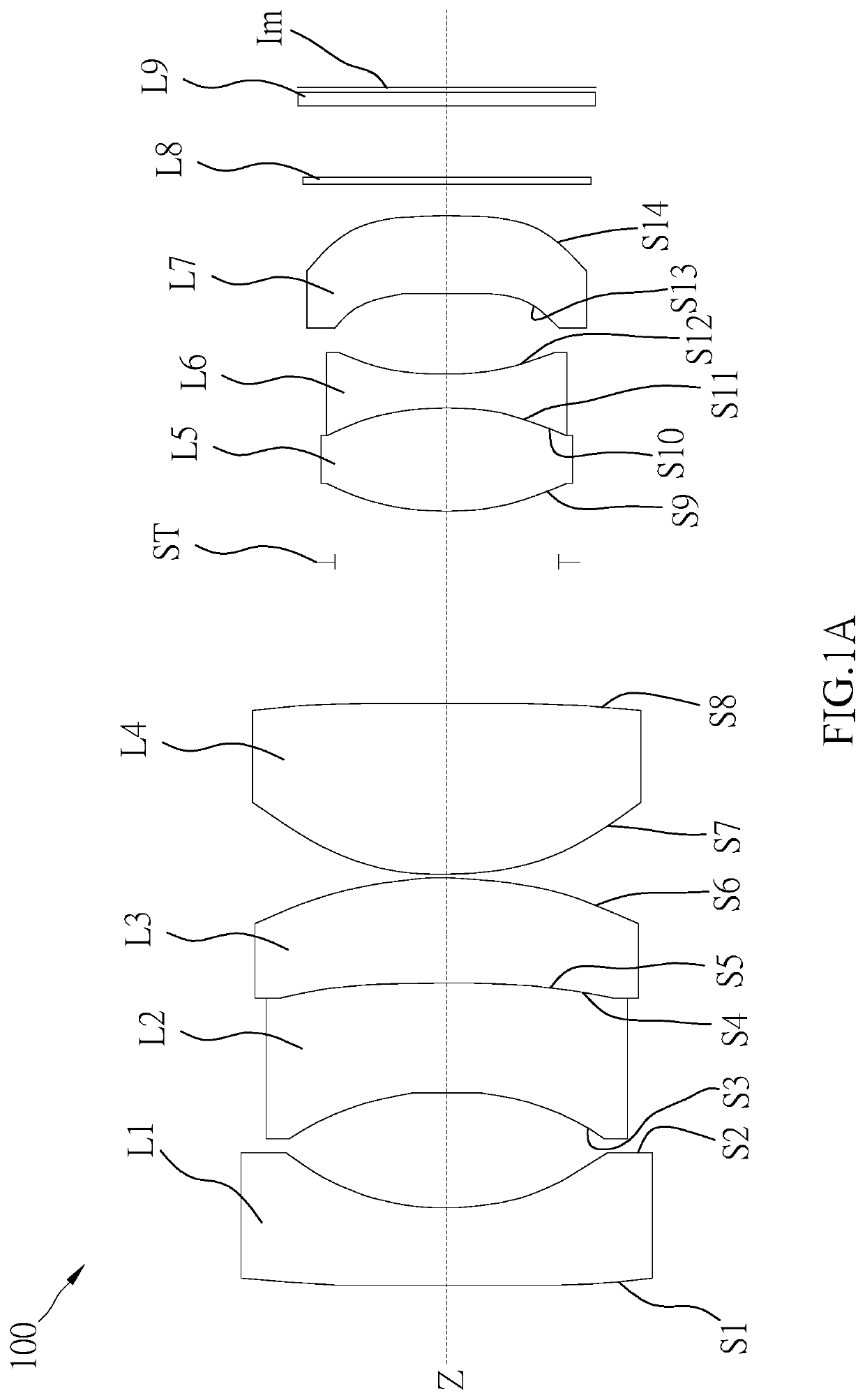
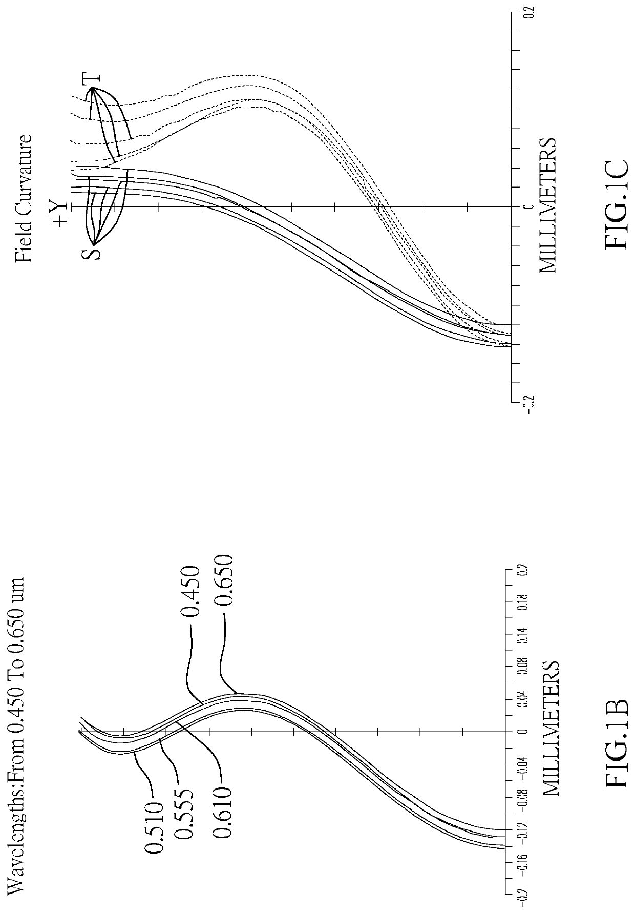
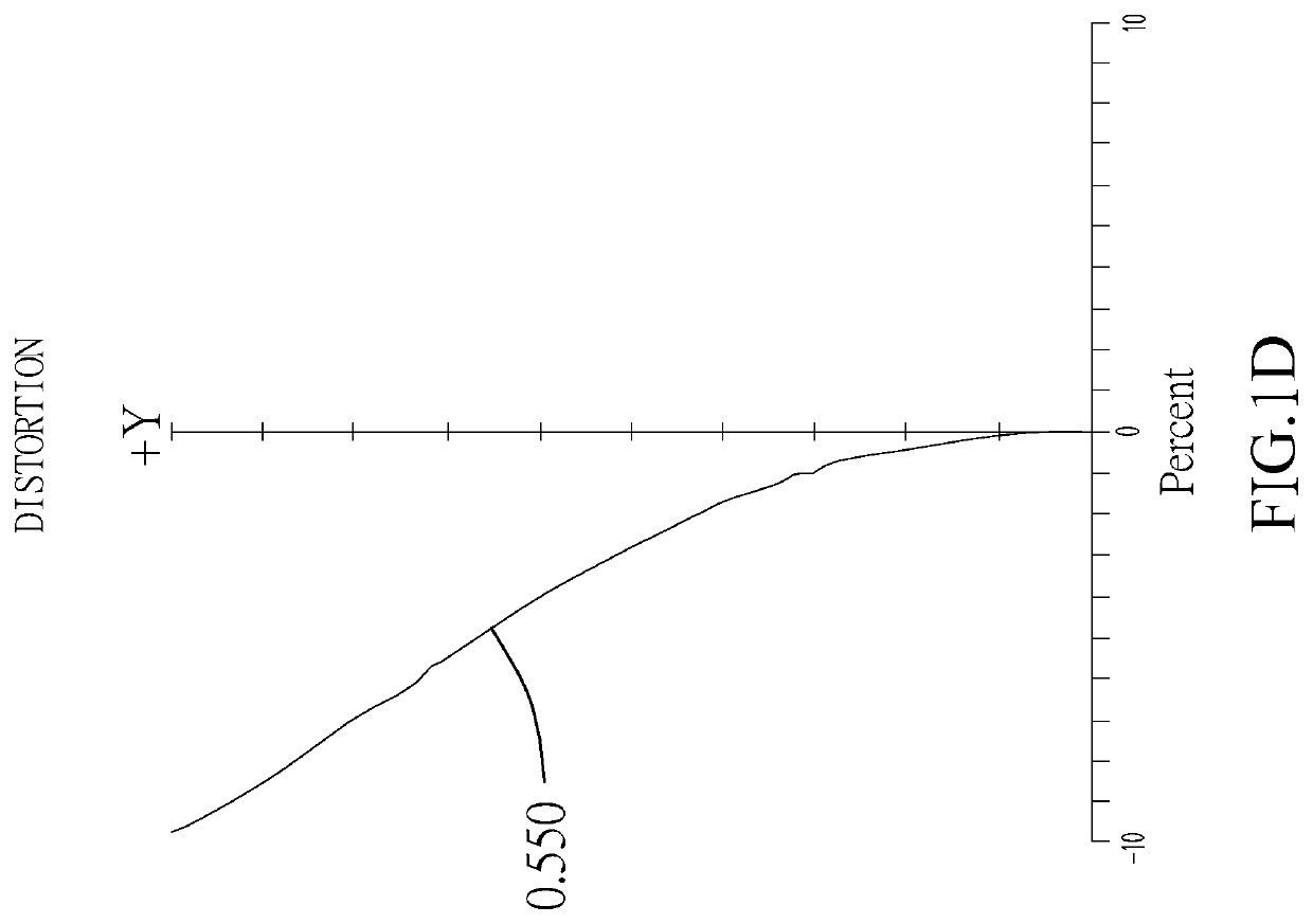
[0021]An optical imaging lens 100 of the present invention is illustrated in FIG. 1A, which includes, in order along an optical axis Z from an object side to an image side, a first lens L1, a second lens L2, a third lens L3, a fourth lens L4, a fifth lens L5, a sixth lens L6, and a seventh lens L7.
[0022]The first lens L1 has negative refractive power, wherein an object-side surface S1 of the first lens L1 is a convex surface toward the object side, and an image-side surface S2 thereof is a concave surface toward the image side.
[0023]The second lens L2 and the third lens L3 are adhered together to form a first compound lens, which could effectively improve a chromatic aberration of the optical imaging lens 100 and reduce an aberration of the optical imaging lens 100. In an embodiment, a cemented surface between the second lens L2 and the third lens L3 could be a flat surface or a convex surface toward the image side. Preferably, in the current embodiment, the first compound lens has ...
second embodiment
[0034]An optical imaging lens 200 of the present invention is illustrated in FIG. 2A, which includes, in order along an optical axis Z from an object side to an image side, a first lens L1, a second lens L2, a third lens L3, a fourth lens L4, a fifth lens L5, a sixth lens L6, and a seventh lens L7.
[0035]The first lens L1 has negative refractive power, wherein an object-side surface S1 of the first lens L1 is a convex surface toward the object side, and an image-side surface S2 thereof is a concave surface toward the image side.
[0036]The second lens L2 and the third lens L3 are adhered together to form a first compound lens, which could effectively improve a chromatic aberration of the optical imaging lens 200 and reduce an aberration of the optical imaging lens 200. In an embodiment, a cemented surface between the second lens L2 and the third lens L3 could be a flat surface or a convex surface toward the image side. Preferably, in the current embodiment, the first compound lens has ...
third embodiment
[0047]An optical imaging lens 300 of the present invention is illustrated in FIG. 3A, which includes, in order along an optical axis Z from an object side to an image side, a first lens L1, a second lens L2, a third lens L3, a fourth lens L4, a fifth lens L5, a sixth lens L6, and a seventh lens L7.
[0048]The first lens L1 has negative refractive power, wherein an object-side surface S1 of the first lens L1 is a convex surface toward the object side, and an image-side surface S2 thereof is a concave surface toward the image side.
[0049]The second lens L2 and the third lens L3 are adhered together to form a first compound lens, which could effectively improve a chromatic aberration of the optical imaging lens 300 and reduce an aberration of the optical imaging lens 300. In an embodiment, a cemented surface between the second lens L2 and the third lens L3 could be a flat surface or a convex surface toward the image side. Preferably, in the current embodiment, the first compound lens has ...
PUM
 Abstract
Description
Claims
Application Information