Supercharge Your Innovation With Domain-Expert AI Agents!

Reactor Containment Building Spent Fuel Pool Filter Vent

Active Publication Date: 2019-05-23
WESTINGHOUSE ELECTRIC CORP
View PDF0 Cites 0 Cited by
  • Summary
  • Abstract
  • Description
  • Claims
  • Application Information

AI Technical Summary

Benefits of technology

The invention relates to a system for handling fuel waste. The system has an outlet that releases atmospheric gas into the waste pool through a sparger, and a chemical injection system that releases chemicals into the pool through a header that is supported above the sparger. The chemicals are injected just above the sparger in the waste pool, which is also supported by a header. This arrangement ensures that the chemicals are released at the lowest possible elevation in the pool, to maximize the time it takes for the gas to escape. Overall, the system optimizes the handling of fuel waste by efficiently releasing gas and chemicals into the waste pool.

Problems solved by technology

However, if a scenario is postulated to be sufficiently severe, the containment vessel itself could fail from gradually increasing pressure.

Method used


Image

  • Reactor Containment Building Spent Fuel Pool Filter Vent

Examples


Embodiment Construction

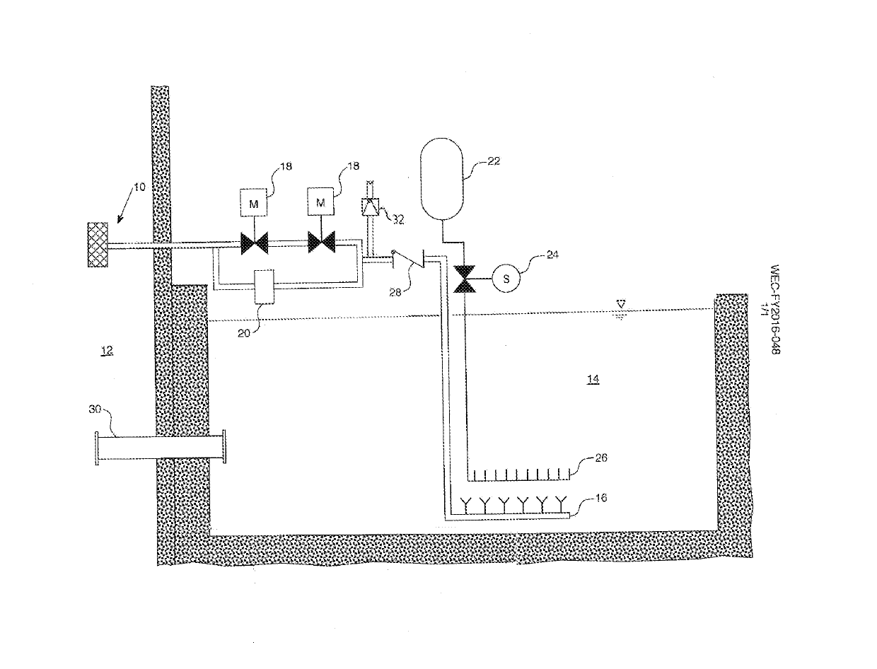
[0011]This invention involves an application specific design of piping, valves, control logic and a chemical injection system to effectively employ the concepts of a wet filtered vent design, such as the one described in U.S. Pat. No. 9,502,144, without the addition of a wet filter vent filtration tank. One embodiment of this invention is illustrated in FIG. 1, which shows a schematic representation of a portion of a nuclear containment and adjacent spent fuel pool. This invention uses ventilation piping 10 that directs a pressure relief discharge from the containment vessel 12 into the planes existing spent fuel pool 14 through an engineered sparger design (or existing spent fuel pool cooling system sparger) 16. Isolation of the ventilation piping is achieved via conventional, remotely operated valve(s) 18, controlled to open by manual actuation by the plant operator. An alternate bypass system, with passive pressure relief valve 20, is available in the event of an operator error o...


PUM


Abstract

A nuclear containment atmospheric filter including dedicated piping, valves, a control system and a chemical injection system to facilitate the use of a commercial nuclear power plant's Spent Fuel Storage Pool and Spent Fuel Storage Pool Cooling System to filter and cool contaminated air and steam vapor released from within a Reactor Containment Vessel / Building preventing vessel overpressure and radioactive release.

Description

BACKGROUND1. Field[0001]This invention pertains in general to nuclear reactor containment systems, and, more particularly, to nuclear reactor containment ventilation filtration systems for safely reducing pressure buildup within a containment without the release of harmful contaminants.2. Related Art[0002]In many jurisdictions, nuclear power plants must be designed to ensure that even in the event of accidents, a mechanism will be provided to prevent or minimize the escape of radioactive material and noble gases. To guard against radioactive releases, the reactor system is typically housed within a primary containment structure that is constructed from steel and reinforced concrete. The primary containment vessel is designed to be capable of withstanding large pressures which may result from various postulated accident scenarios. However, if a scenario is postulated to be sufficiently severe, the containment vessel itself could fail from gradually increasing pressure. Although the l...

Claims


Application Information

Patent Timeline
IPC IPC(8): G21C13/10G21C19/07G21C9/004G21C13/02G21C19/307
CPCG21C13/10G21C19/07G21C9/004G21C13/022G21C19/307G21Y2002/50G21Y2002/501G21Y2004/20G21C19/303Y02E30/30G21C19/00
Inventor FERRARACCIO, FRANCIS P.JAEGER, TIMOTHY P.
Owner WESTINGHOUSE ELECTRIC CORP
Features
  • R&D
  • Intellectual Property
  • Life Sciences
  • Materials
  • Tech Scout
  • Unparalleled Data Quality
  • Higher Quality Content
  • 60% Fewer Hallucinations
Learn More