Apparatus and method for supplying pulse to solvent extraction column

a technology of solvent extraction and apparatus, which is applied in the direction of nuclear elements, greenhouse gas reduction, separation processes, etc., can solve the problems of high cost, difficult to achieve and equipment having a small size and high reliability, so as to reduce the investment cost of solvent extraction process and stable operation of pulsed columns. , the effect of stable operation

Inactive Publication Date: 2019-05-23
KEPCO NUCLEAR FUEL CO LTD
View PDF10 Cites 0 Cited by
  • Summary
  • Abstract
  • Description
  • Claims
  • Application Information

AI Technical Summary

Benefits of technology

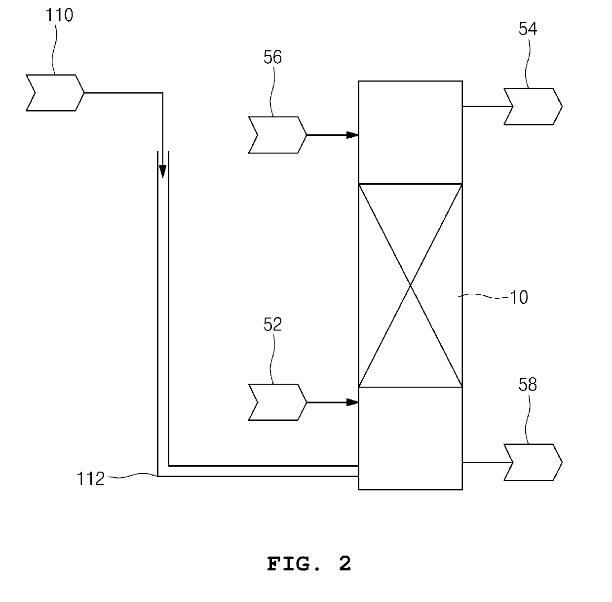
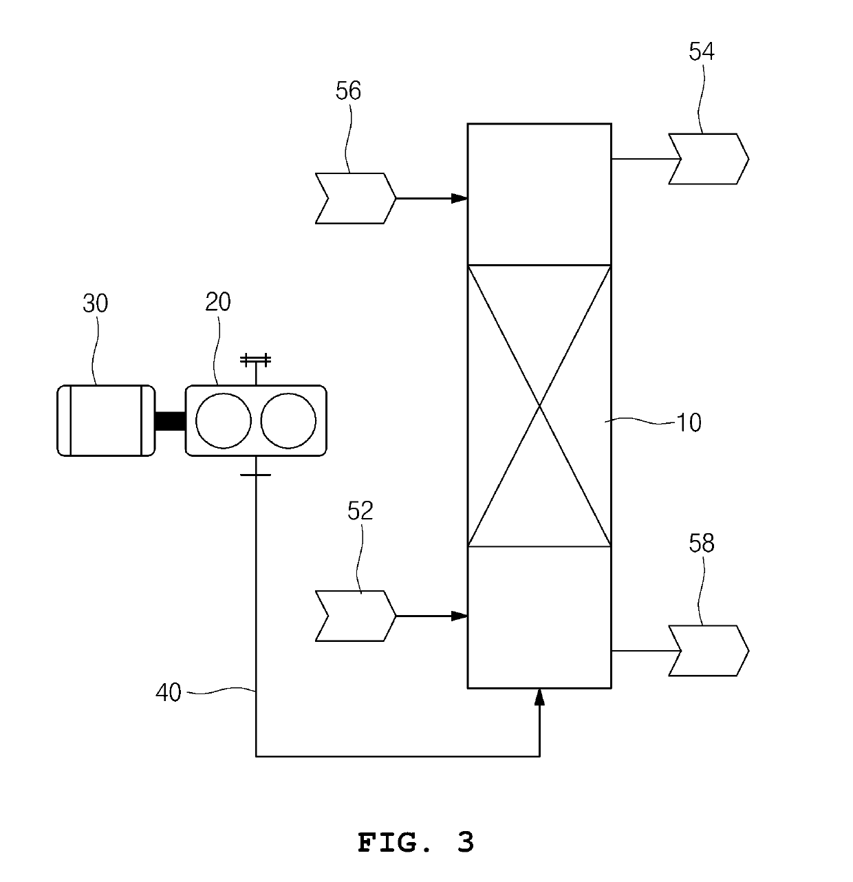
[0017]Accordingly, the present invention has been made keeping in mind the above problems occurring in the related art, and the present invention is intended to propose a low cost apparatus and a simple method for stably supplying pulse to a pulsed column that is employed as unit equipment in solvent extraction process.
[0018]Further, another object of the present invention is to propose an apparatus that stably supplies a pulse to a pulsed column, thereby preventing channeling of fluid in the pulsed column and preventing flooding of fluid at the top part of the pulsed column thereof in solvent extraction process.
[0026]According to the present invention, in a uranium separation and refinement process in which uranium is separated and refined from an aqueous nitric or sulfuric acid solution containing dissolved uranium by using an extracting solvent, the solvent extraction column can be stably operated without channeling of fluid in the pulsed column, and flooding of fluid at the top part of the pulsed column thereof.
[0027]Further, according to a result of an experiment carried out to separated and refined uranium from a nitric acid solution containing uranium and impurities, an extraction efficiency of about 90.2% is obtained. Thus, the result that fully satisfies the specification of impurities for uranium dioxide used in nuclear fuel production cab be achieved.
[0028]Therefore, when supplying a pulse to the pulsed column according to the present invention, the present invention can achieve reduction in investment costs for solvent extraction process compared with a conventional apparatus for supplying a pulse. Further, the present invention enables a stable operation of the pulsed column with a simple method.

Problems solved by technology

Moreover, unit equipment for treating nuclear fuel materials uses geometry control in consideration of nuclear criticality safety control, so it requires equipment having a small size and high reliability.
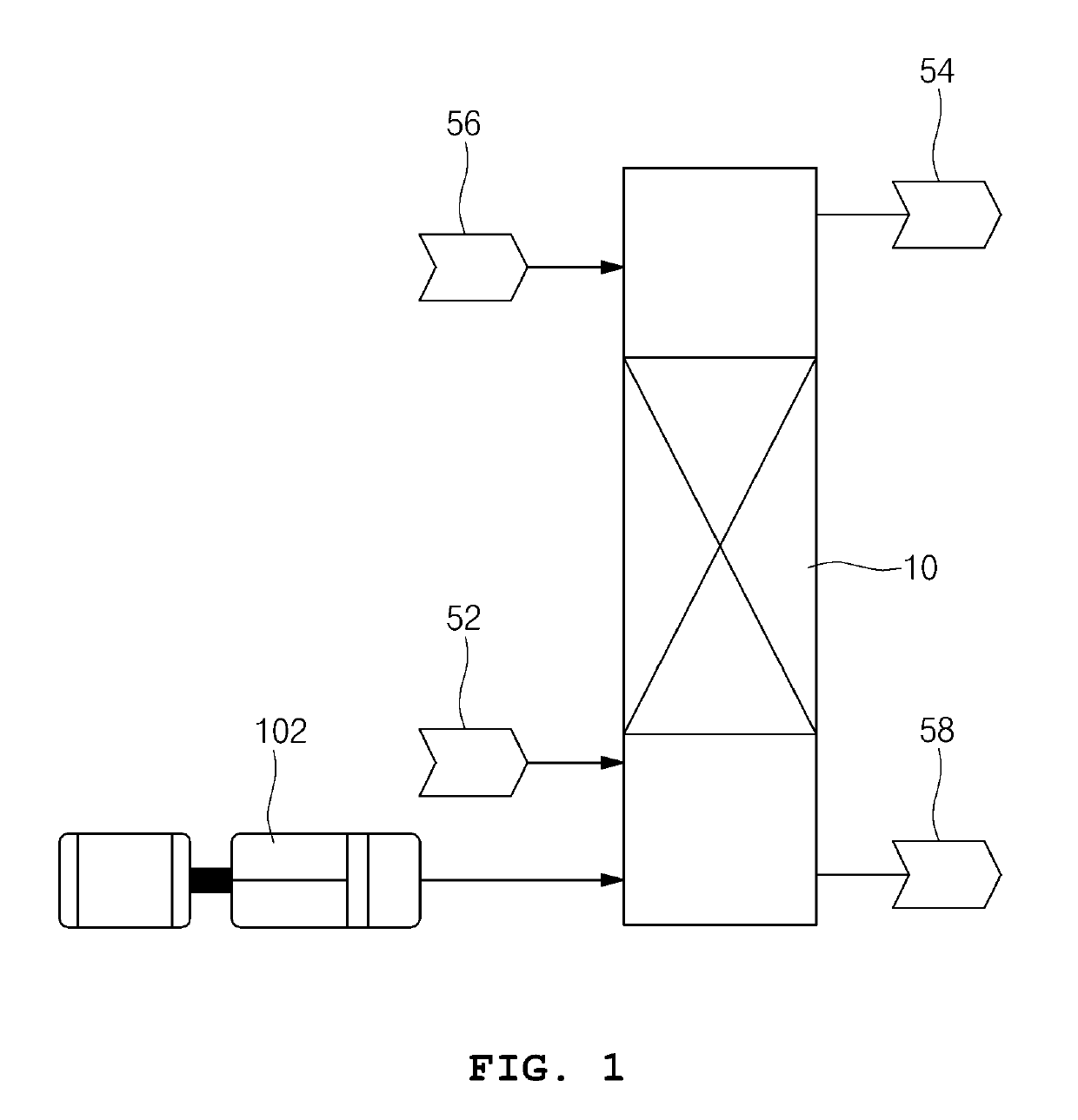
However, the conventional solvent extraction process using pulsed columns is problematic in that the apparatus for supplying a pulse to the pulsed column requires high costs, and it is difficult to achieve stable operation of a pulsed column due to difficulty in control of the pulse supply.
Moreover, the conventional solvent extraction process using pulsed columns is further problematic in that as capacity of the pulsed column is increased, investment costs and an installation area of the apparatus for supplying a pulse are increased.
Thus, the apparatus is not easily applied for use.
Further, resistance against the apparatus 102 for supplying a pulse is increased, so it is difficult to achieve stable operation thereof in solvent extraction process.
Accordingly, a pulse is generated by pressure of a compressive fluid, so it is difficult to stably supply the pulse to the pulsed column.
As such, absence of a stable pulse causes channeling of fluid in the pulsed column and flooding of fluid at the top part of the pulsed column thereof.
Thus, there is a problem in that it leads to reduction in stability and efficiency of solvent extraction process.

Method used


Image

  • Apparatus and method for supplying pulse to solvent extraction column
  • Apparatus and method for supplying pulse to solvent extraction column
  • Apparatus and method for supplying pulse to solvent extraction column

Examples


Embodiment Construction

[0033]Specific structural and functional descriptions of embodiments of the present invention disclosed herein are only for illustrative purposes of the embodiments of the present invention. The present invention may be embodied in many different forms without departing from the spirit and significant characteristics of the present invention. Therefore, the embodiments of the present invention are disclosed only for illustrative purposes and should not be construed as limiting the present invention.

[0034]It will be understood that, although the terms first, second, etc. may be used herein to describe various elements, these elements should not be limited by these terms. These terms are only used to distinguish one element from another element. For instance, a first element discussed below could be termed a second element without departing from the teachings of the present invention. Similarly, the second element could also be termed the first element.

[0035]It will be understood that...


PUM


Abstract

Disclosed are an apparatus and a method for supplying a pulse to solvent extraction column (hereinafter, pulsed column). More particularly, the present invention relates to a low cost apparatus with a simple method for stably supplying a pulse to a pulsed column, which is employed as unit equipment in a solvent extraction process. The apparatus for supplying a pulse to the pulsed column having a first solvent inlet and a second solvent outlet at the low part of the pulsed column, and a second solvent inlet and a first solvent outlet at the top part of the pulsed column thereof, includes: a diaphragm pump actuated by using electric power or compressed air, and having a discharge part and a suction part, in which one of the discharge part and the suction part is blinded while the remaining one thereof is connected to the pulsed column via a pulse supply line.

Description

CROSS REFERENCE TO RELATED APPLICATION[0001]This application is a divisional application of co-pending U.S. application Ser. No. 15 / 334,630, filed Oct. 26, 2016, the disclosure of which is incorporated herein by reference. This application claims priority benefits under 35 U.S.C. § 1.119 to Korean Patent Application No. 10-2016-0096020 filed Jul. 28, 2016.BACKGROUND OF THE INVENTIONField of the Invention[0002]The present invention relates generally to an apparatus and a method for supplying a pulse to a solvent extraction column (hereinafter, pulsed column). More particularly, the present invention relates to a low cost apparatus with a simple method for stably supplying a pulse to a pulsed column, which is employed as unit equipment in a solvent extraction process.Description of the Related Art[0003]In general, solvent extraction process is employed in separation and refinement of a desired solute, in which the desired solute is selectively extracted from inert materials by a metho...

Claims


Application Information

Patent Timeline
Patent Type & Authority Applications(United States)
IPC IPC(8): G21F9/04B01D11/04F04B43/04F04B43/06
CPCG21F9/04B01D11/0438B01D11/04F04B43/04F04B43/06Y02E30/30B01D11/02B01J19/18G21C19/46
Inventor BAE, YOUNGMOONYANG, SEUNGCHULLEE, BYUNGKUKKWAK, DONGYONGCHO, HYUNKWANG
Owner KEPCO NUCLEAR FUEL CO LTD
Why Eureka
Try Eureka