RF signal switching, phase shifting and polarization control

a phase shift and phase control technology, applied in waveguide devices, frequency-independent attenuators, antennas, etc., can solve the problems of large chip area, degrade signal quality, and amenable techniques at rf and mmwave frequencies

Active Publication Date: 2019-05-23
IBM CORP
View PDF0 Cites 21 Cited by
  • Summary
  • Abstract
  • Description
  • Claims
  • Application Information

AI Technical Summary

Benefits of technology

[0004]An apparatus includes first and second electronically tunable transmission lines configured to transmit or receive a signal pair and provide a selected phase delay difference to the signal pair corresponding to a selected polarization, a first attenuation element connected to the first electronically tunable transmission line and a second attenuation element connected to the second electronically tunable transmission line. The first and second attenuation elements may each be configured to selectively attenuate signals carried on the electronically tunable transmission line to which they are connected according to a selected attenuation setting of a plurality of selectable attenuation settings provided by one or more attenuation control signals and thereby provide a selected attenuation to the signal pair that corresponds to the selected polarization. A corresponding method is also disclosed herein.

Problems solved by technology

While a number of techniques to achieve signal switching, phase shifting and polarization control in optical systems exist, these techniques are not amenable at RF and mmWave frequencies.
However, the large number of circuit components used to achieve signal switching, phase shifting and polarization control consume a large chip area and degrade signal quality.
Moreover, despite the large area and signal degradation introduced by such systems, these systems provide only coarse polarization control, by selecting from a few fixed polarization modes.
Mechanical control of polarization is also possible but tends to be extremely slow and cumbersome.

Method used


Image

  • RF signal switching, phase shifting and polarization control
  • RF signal switching, phase shifting and polarization control
  • RF signal switching, phase shifting and polarization control

Examples


Embodiment Construction

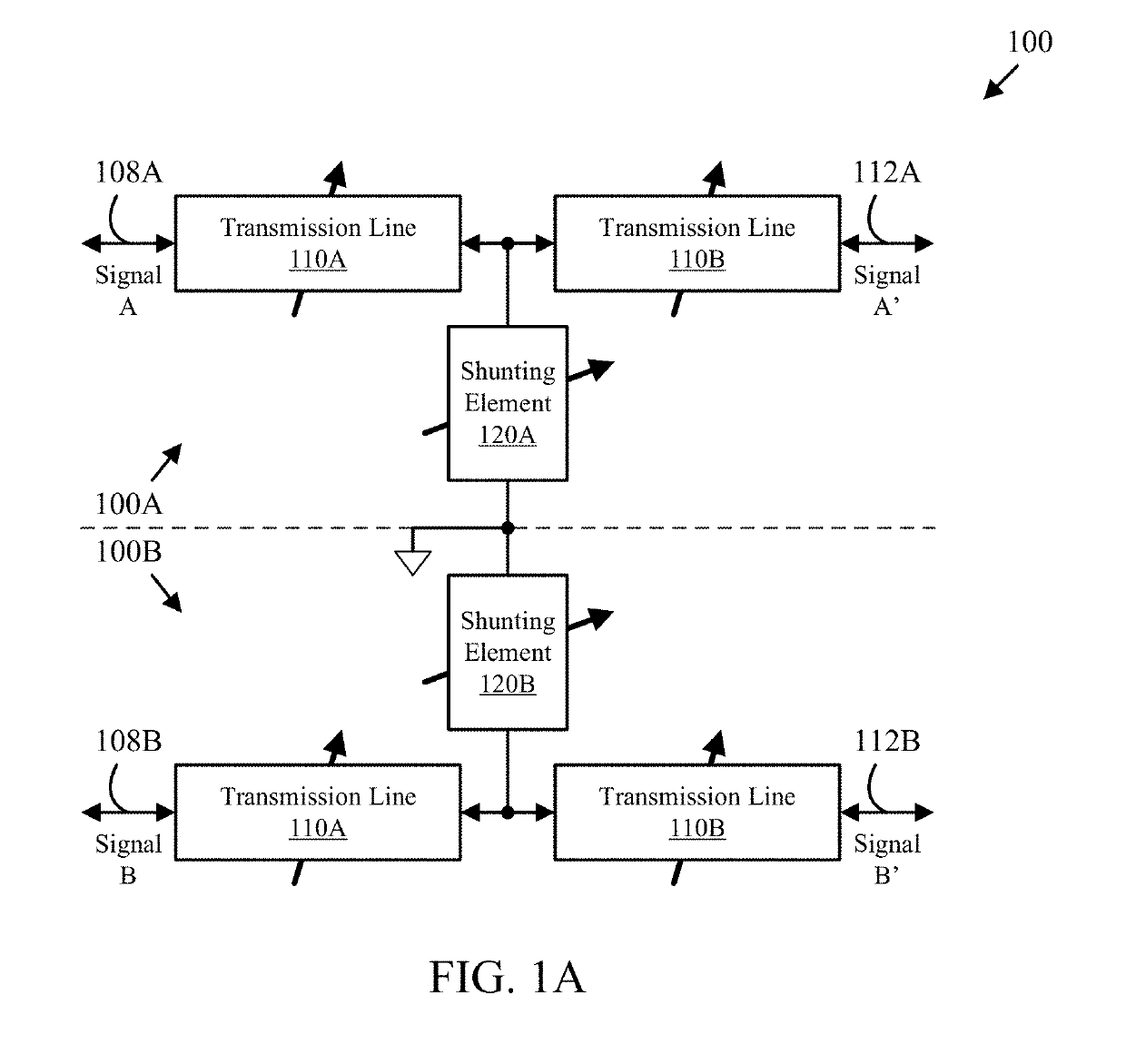
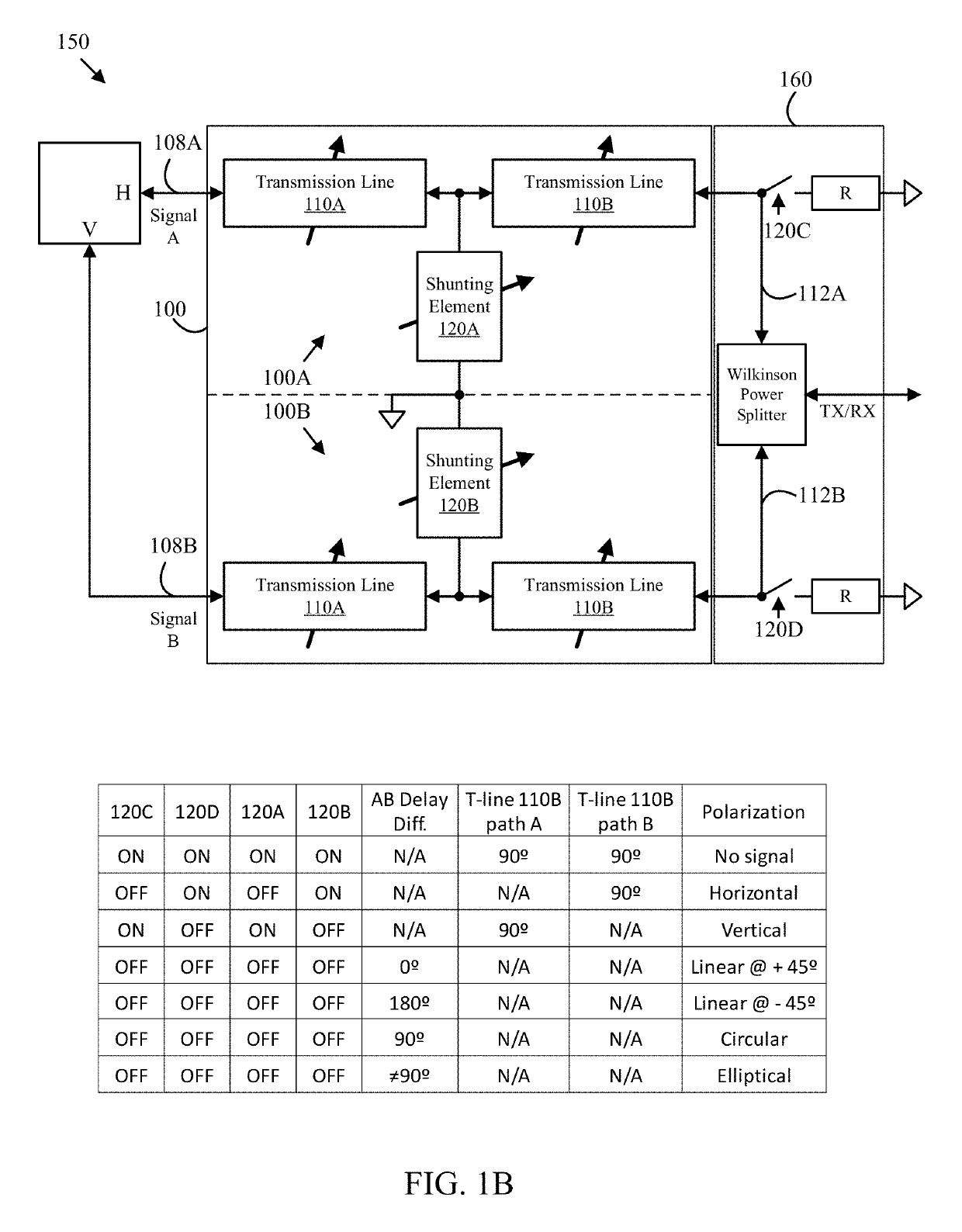
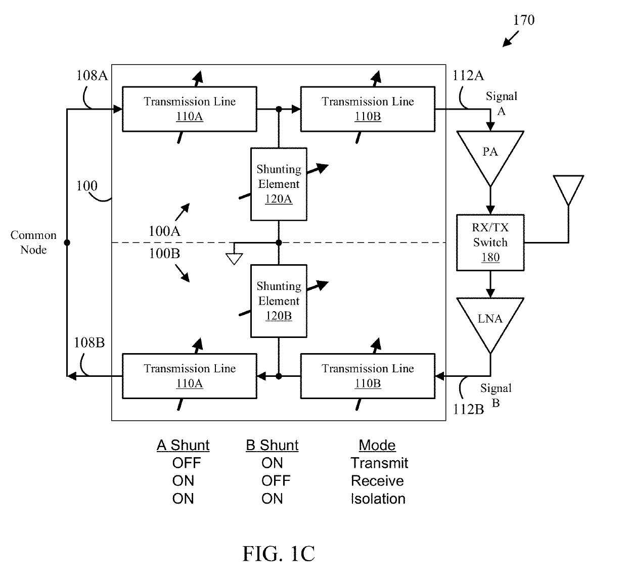
[0013]At least some of the embodiments disclosed herein recognize that many RF circuits such as antenna array controllers require switching, selectable phase shifting and polarization control functions.

[0014]It should be noted that references throughout this specification to features, advantages, or similar language herein do not imply that all of the features and advantages that may be realized with the embodiments disclosed herein should be, or are in, any single embodiment of the invention. Rather, language referring to the features and advantages is understood to mean that a specific feature, advantage, or characteristic described in connection with an embodiment is included in at least one embodiment of the present invention. Thus, discussion of the features, advantages, and similar language, throughout this specification may, but do not necessarily, refer to the same embodiment.

[0015]Furthermore, the described features, advantages, and characteristics of the invention may be c...


PUM


Abstract

An apparatus includes first and second electronically tunable transmission lines configured to transmit or receive a signal pair and provide a selected phase delay difference to the signal pair corresponding to a selected polarization, a first attenuation element connected to the first electronically tunable transmission line and a second attenuation element connected to the second electronically tunable transmission line. The first and second attenuation elements may each be configured to selectively attenuate signals carried on the electronically tunable transmission line to which they are connected according to a selected attenuation setting of a plurality of selectable attenuation settings provided by one or more attenuation control signals and thereby provide a selected attenuation to the signal pair that corresponds to the selected polarization. A corresponding method is also disclosed herein.

Description

STATEMENT REGARDING FEDERALLY SPONSORED RESEARCH OR DEVELOPMENT[0001]This invention was made with U.S. Government support under contract number FA8650-09-C-7924 awarded by the Department of Defense. The U.S. Government has certain rights to this invention.BACKGROUND OF THE INVENTION[0002]The present invention relates generally to electronic circuits such as integrated circuits, and more particularly to integrated RF circuits.[0003]Signal switching, phase shifting, and polarization control are commonly needed in RF circuits. For example, phased array antenna systems may select which antennas are active and the phase delay associated with each active antenna and the type of polarization used in signal transmission and reception. While a number of techniques to achieve signal switching, phase shifting and polarization control in optical systems exist, these techniques are not amenable at RF and mmWave frequencies. At mmWave frequencies, electronically controlled signal switching, phase...

Claims


Application Information

Patent Timeline
Patent Type & Authority Applications(United States)
IPC IPC(8): H03H11/24H03H11/20H01Q3/36H01Q15/24
CPCH03H11/245H03H11/20H01Q3/36H01Q15/24H01P1/127H01P1/184H01P1/227H01Q21/245
Inventor VALDES GARCIA, ALBERTOWOODS, JR., WAYNE H.SADHU, BODHISATWA
Owner IBM CORP
Why Eureka
Try Eureka