Endoscopic system, over-tube, and cap

a technology of endoscope and overtube, which is applied in the field of endoscope system, can solve the problems of difficult visual recognition of identifiers and dented identifiers, and achieve the effects of increasing cross-sectional area, increasing visibility, and preventing the lower insertability of endoscopes

Inactive Publication Date: 2019-05-30
OLYMPUS CORP
View PDF0 Cites 1 Cited by
  • Summary
  • Abstract
  • Description
  • Claims
  • Application Information

AI Technical Summary

Benefits of technology

[0008]With the above embodiment, an endoscope is inserted into the endoscope channel of the tubular member, and then captures an image of an inner surface of the endoscope channel. The endoscope captures an image that includes the protrusion that protrudes radially inwardly from at least the portion of the inner circumferential surface of the endoscope channel in the longitudinal direction thereof. The protrusion in the acquired image makes it possible for the user to confirm the position configuration of the treatment tool channel in a circumferential direction with respect to the endoscope channel. In other words, the protrusion lets the user know in what position configuration the treatment tool will appear in an endoscopic image before the treatment tool projects from the distal end of the tubular member through the treatment tool channel and appears in the endoscopic image. The protrusion may be disposed on a straight line interconnecting the center of the endoscope channel and the center of the treatment tool channel. The protrusion makes it easy for the user to know in the endoscopic image that the treatment tool channel exists on an extension of a straight line interconnecting the center of the image and the protrusion in the image. The protrusion may be disposed in the vicinity of the distal end of the endoscope channel in the longitudinal direction thereof.
[0009]With this arrangement, even if the over-tube is twisted and the treatment tool channel is in different positions with respect to the endoscope channel at the proximal end and the distal end of the over-tube, the user can confirm the position of the treatment tool channel in the circumferential direction by the protrusion. The protrusion is disposed in the vicinity of the distal end and the endoscope will project from the distal end. Therefore, the practitioner would know properly in which position configuration the treatment tool will appear in the endoscopic image. The protrusion may be elastically deformable radially outwardly by being pushed by the endoscope inserted in the endoscope channel. When the endoscope is apart from the protrusion, the protrusion protrudes radially inwardly to a large extent, increasing its visibility in the endoscopic image. After the endoscope is contacted the protrusion, the protrusion is elastically deformed radially outwardly by the endoscope, increasing the cross-sectional area of a passage through which the endoscope passes thereby to prevent the insertability of the endoscope from being lowered. The protrusion may have a slope which protrudes radially inwardly by a distance that progressively varies from the proximal end toward the distal end of the endoscope channel. Although the protrusion reduces the cross-sectional area of a passage for endoscope to travel, the slope of the protrusion can guide the endoscope as it moves from the proximal end toward the distal end of the over-tube to go easily over the protrusion, thereby preventing the insertability of the endoscope from being lowered. The protrusion may have a shape which is different for each treatment tool channel. With this arrangement, it is possible to identify the type of the treatment tool channel by confirming the shape of the protrusion in the endoscopic image acquired by the endoscope.
[0010]According to another embodiment of the technology disclosed herein, a cap is mounted on the distal end of an elongated over-tube. The elongated over-tube includes a tubular member having a treatment tool channel into which a treatment tool is inserted and an endoscope channel into which an endoscope is inserted. The cap includes a treatment tool exit hole, an endoscope exit hole, and a protrusion. The treatment tool exit hole is defined at a position that is held in fluid communication with the treatment tool channel. The endoscope exit hole is defined at a position that is held in fluid communication with the endoscope channel. The protrusion protrudes radially inwardly from an inner circumferential surface of the endoscope exit hole. The protrusion indicates a circumferential position of the treatment tool exit hole with respect to the endoscope exit hole. The cap is mounted on the distal end of the over-tube. The endoscope channel in the over-tube and the endoscope exit hole in the cap are held in fluid communication with each other. The treatment tool channel in the over-tube and the treatment tool exit hole in the cap are held in fluid communication with each other. When an endoscope is placed in the endoscope channel and captures an endoscopic image, the endoscopic image includes the protrusion that protrudes radially inwardly from the inner circumferential surface of the endoscope exit hole. The protrusion in the endoscopic image lets the user know in which position the treatment tool will appear in the endoscopic image before the treatment tool projects from the treatment tool exit hole through the treatment tool channel and appears in the endoscopic image.
[0011]According to still further embodiment of the technology disclosed herein, an endoscopic system includes any one of the described-herein over-tubes, an endoscope that is inserted in the endoscope channel in the over-tube, and the treatment tool that is inserted in the treatment tool channel in the over-tube. The technology disclosed herein offers the advantages such as to identify with greater certainty from which position a medical instrument inserted in a channel will project on the distal end of an elongated over-tube.

Problems solved by technology

However, when the identifier is formed by denting a portion of the inner surface of the channel, the identifier is often difficult to visually recognize with an observational instrument inserted in the channel.
In particular, if a body fluid or the like is deposited in the channel, then the dented identifier tends to be filled up with the body fluid or the like, and hence the dented identifier becomes more difficult to be visually recognized.

Method used


Image

  • Endoscopic system, over-tube, and cap
  • Endoscopic system, over-tube, and cap
  • Endoscopic system, over-tube, and cap

Examples


Embodiment Construction

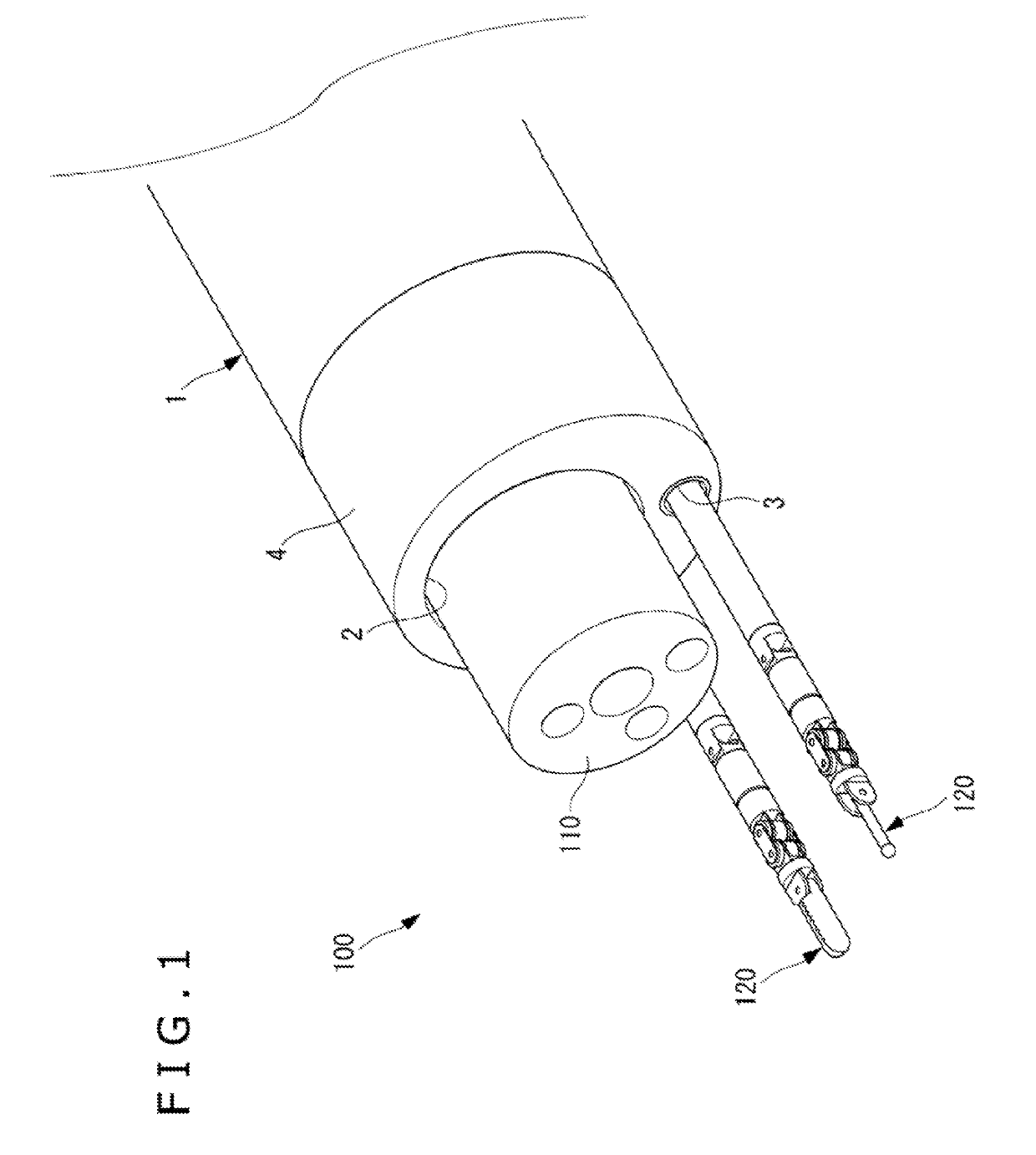
[0006]Embodiments of the technology disclosed herein is directed to an elongated over-tube, an endoscopic system, and a cap which is constructed to identify with greater certainty from which position a medical instrument inserted in a channel will project on the distal end of the elongated over-tube.

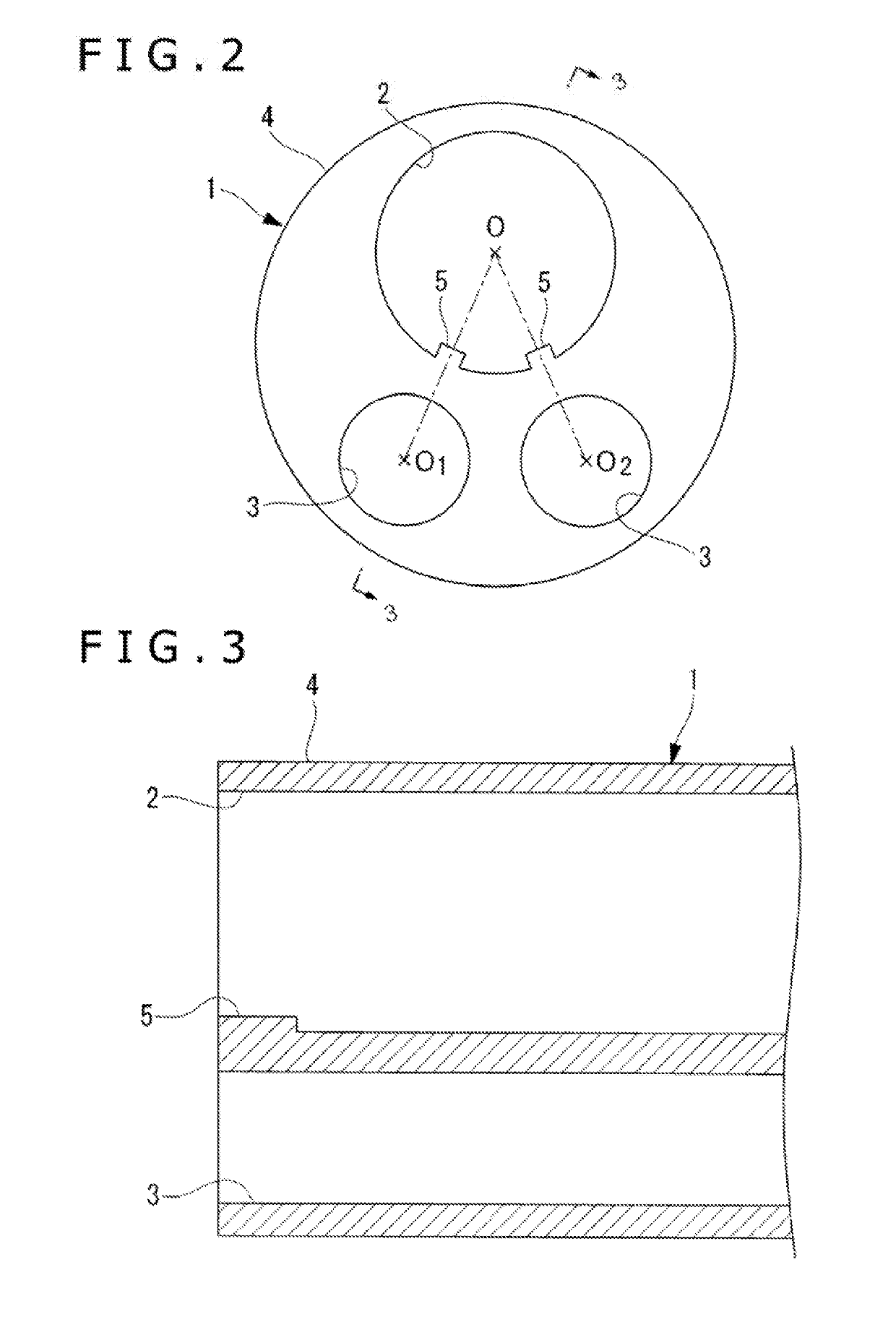
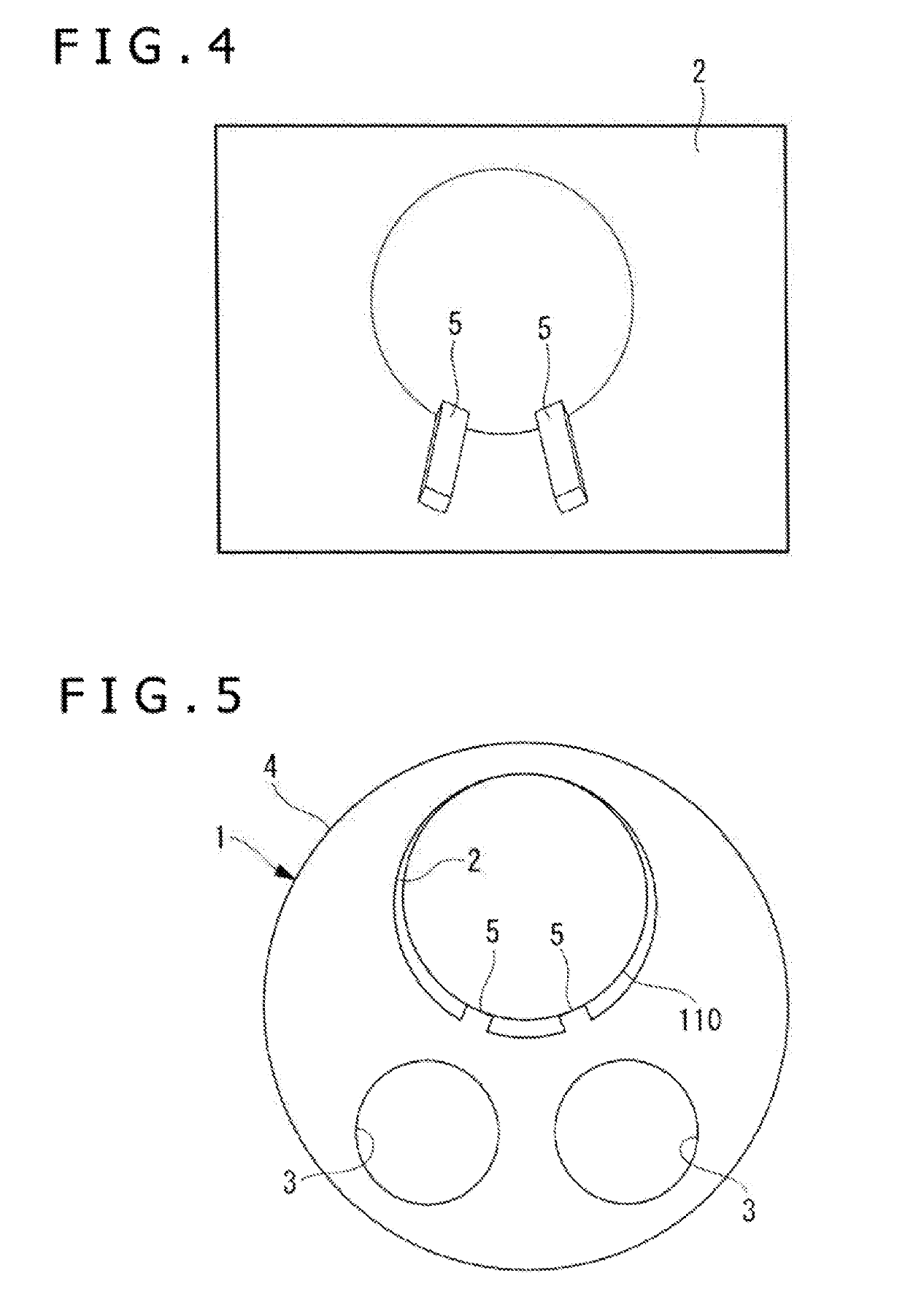
[0007]According to one embodiment of the technology disclosed herein, an elongated over-tube includes an elongated tubular member and a protrusion. The elongated tubular member includes a treatment tool channel into which a treatment tool can be inserted and an endoscope channel into which an endoscope can be inserted. The protrusion protrudes radially inwardly from at least a portion of an inner circumferential surface of the endoscope channel in a longitudinal direction thereof. The protrusion indicates a direction that the treatment tool channel exists with respect to the endoscope channel.

[0008]With the above embodiment, an endoscope is inserted into the endoscope channel of the tubu...


PUM


Abstract

The technology disclosed herein is directed to an over-tube, an endoscopic system, and a cap which is constructed to identify with greater certainty from which position a medical instrument inserted in a channel will project on the distal end of the over-tube. The over-tube includes a tubular member and a protrusion. The tubular member includes at least a treatment tool channel into which a treatment tool is inserted and an endoscope channel into which an endoscope device is inserted. The protrusion protrudes radially inwardly from at least a portion of an inner circumferential surface of the endoscope channel in a longitudinal direction thereof. The protrusion indicates a position configuration in a circumferential direction of the treatment tool channel with respect to the endoscope channel. The endoscope captures an image that includes the protrusion and the protrusion in the acquired image confirms the position configuration of the treatment tool channel.

Description

CROSS-REFERENCE TO RELATED APPLICATION[0001]This application is a continuation application of PCT Application No. PCT / JP2016 / 086132 filed on Dec. 6, 2016, which is hereby incorporated by reference in its entirety.TECHNICAL FIELD[0002]The technology disclosed herein relates generally to an endoscopic system, and more particularly, some embodiments relate to a combination of an over-tube, an endoscopic system, and a cap.DESCRIPTION OF THE RELATED ART[0003]A Japanese Patent Application JP 2013-172780A discloses an over-tube having an identifier formed by radially outwardly denting a portion of the inner circumferential surface of a channel in the over-tube. The identifier is visually recognized with a medical instrument inserted in the channel. A user can recognize from which position the medical instrument is inserted in the channel so that it projects on the distal end of the over-tube.[0004]However, when the identifier is formed by denting a portion of the inner surface of the chann...

Claims


Application Information

Patent Timeline
Patent Type & Authority Applications(United States)
IPC IPC(8): A61B1/00A61B1/018A61B1/05
CPCA61B1/00135A61B1/00087A61B1/018A61B1/05A61B1/00154A61B1/01A61B1/00101A61B1/00137
Inventor WAKASONE, JUNISODA, TAKUMI
Owner OLYMPUS CORP
Why Eureka
Try Eureka