Sensor installation structure

a technology for installing structures and sensors, applied in bumpers, instruments, vehicle components, etc., can solve problems such as poor sensing, deterioration of external appearance (the look) of vehicles, and poor sensing

a technology for installing structures and sensors, applied in bumpers, instruments, vehicle components, etc., can solve problems such as poor sensing, deterioration of external appearance (the look) of vehicles, and poor sensing

US20190162845A1Active Publication Date: 2019-05-30TOYOTA JIDOSHA KK

Image

  • Sensor installation structure
  • Sensor installation structure
  • Sensor installation structure

Examples


Embodiment Construction

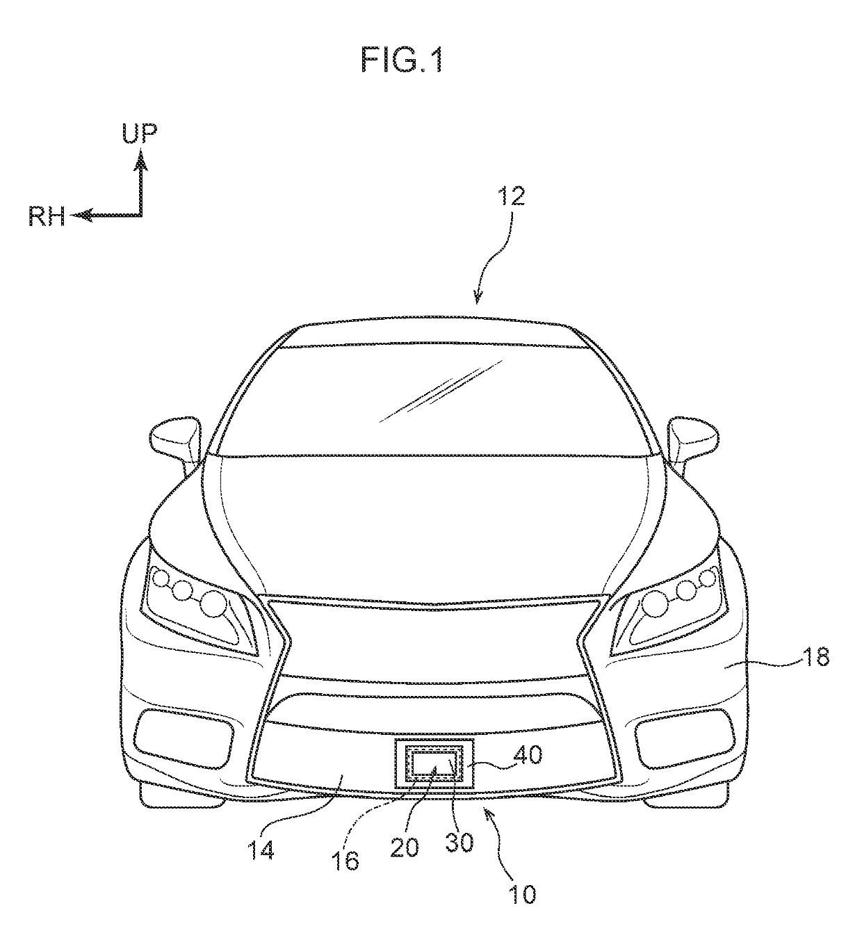
[0029]An embodiment relating to the present disclosure is described in detail hereinafter on the basis of the drawings. Note that, for convenience of explanation, arrow UP that is shown appropriately in the respective drawings indicates the vehicle upward direction, arrow FR indicates the vehicle frontward direction, and arrow RH indicates the vehicle rightward direction. Accordingly, in the following description, when vertical, longitudinal, and left-right directions are used without being specified, they refer to the vertical of the vehicle vertical direction, the longitudinal of the vehicle longitudinal direction, and the left and right of the vehicle left-right direction (the vehicle transverse direction).

[0030]As shown in FIG. 1, a sensor 20, which senses periphery information of a vehicle 12 by using infrared laser light for example, is provided at the lower portion of the vehicle transverse direction center of a front grill 14 that serves as an exterior member of the vehicle ...


PUM


Abstract

A sensor installation structure includes: a sensor that has a sensing portion that senses periphery information of a vehicle; an exterior member having an opening portion that exposes the sensing portion , the opening portion being configured so as to allow changes in an angle of the sensing portion; and a cover member that is provided at an outer edge portion of the sensing portion, the cover member covering a gap between the outer edge portion of the sensing portion and a peripheral edge portion of the opening portion such that the gap cannot be seen from an exterior.

Description

CROSS-REFERENCE TO RELATED APPLICATION[0001]This application is based on and claims priority under 35 USC 119from Japanese Patent Application No. 2017-228124 filed on Nov. 28, 2017, the disclosure of which is incorporated by reference herein.BACKGROUNDTechnical Field[0002]The present disclosure relates to a sensor installation structure.Related Art[0003]There has conventionally been proposed a sonar sensor mounting structure in which a sonar sensor, which detects the distance to an object of sensing by transmitting ultrasonic waves from a sensing surface of a sensor main body and receiving reflected waves of the ultrasonic waves that have been reflected by the object of sensing, is mounted to a bumper (see, for example, International Publication No. 2012 / 144270 (Patent Document 1)). In this sonar sensor, a cover portion, which is made of resin and covers the sensing surface, is inserted into a hole portion formed in the bumper, and the outer surface of the cover portion is made to b...

Claims


Application Information

Patent Timeline
30 May 2019
Publication
US20190162845A1
IPC
G01S15/02; B60R19/48; G01S7/521; G01S15/931
CPC
G01S15/02; B60R19/483; G01S7/521; G01S2015/938; G01S15/931
Inventors
YASUI, YOHSUKE