Method for identifying optimum runway orientation

Inactive Publication Date: 2019-05-30
ANADOLU UNIVSI
View PDF2 Cites 0 Cited by
  • Summary
  • Abstract
  • Description
  • Claims
  • Application Information

AI Technical Summary

Benefits of technology

[0010]In conclusion, the method of the invention not only produces more accurate results when compared to the previously developed models as it eliminates the sour

Problems solved by technology

In particular, a strong cross-wind perpendicular to the take-off or landing direction might prevent safe maneuvering of the airplane to on the runway.
The most significant problem in the wind rose technique is the cells that do not fall completely within t

Method used


Image

  • Method for identifying optimum runway orientation
  • Method for identifying optimum runway orientation
  • Method for identifying optimum runway orientation

Examples


Embodiment Construction

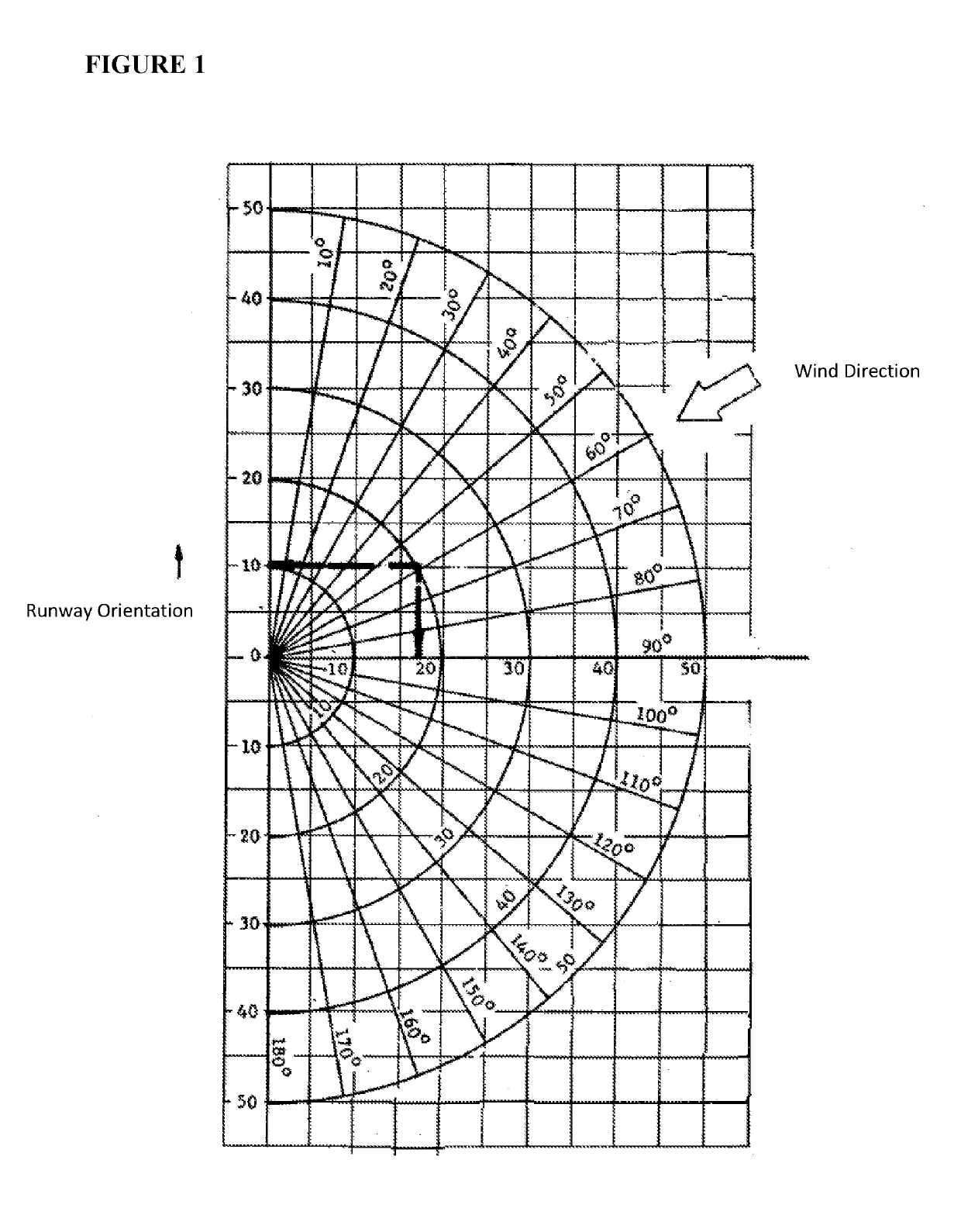
[0019]The method of the invention applied in computer produces solutions for two different types of analyses. First type of analysis calculates the optimum runway configuration that produces the highest usability factor automatically. In the second analysis method, on the other hand, the usability factor is calculated based on the previously identified runway orientations (e.g. orientations of 20° / 200°, 30° / 210° . . . 160° / 340°), where it is possible to determine whether the selected runway orientations are suitable, in other words whether the usability factor is higher than the predetermined value (e.g. 95%).

[0020]The method of the invention applied in computer that performs the first and second types of analyses mentioned above are executed by an electronic device (e.g. smart devices such as a computer, tablet computer, smart phone, etc.) that contains a database (e.g. hard disk, flash disk, external hard disk, CD, internet database (e.g. cloud database) etc.), a control unit, a u...


PUM


Abstract

The present invention relates to a method applied with a computer that allows identification of the optimum runway orientation that produces the highest usability factor and also identification of the usability factor based on the previously identified runway configuration by using an electronic device containing a database, a control unit, a data input interface, a user interface and a display.

Description

FIELD OF THE INVENTION[0001]The present invention relates to a method that allows identification of the optimum runway orientation that provides the highest usability factor and that enables identification of the usability factors also for two or three different runway configurations predefined by the user. The method developed herein can be used for airport planning and design as intended for identification of the optimum runway orientation / orientations in the airline transport sector.BACKGROUND[0002]When constructing a new airport, or when adding a new runway to an existing airport, a technique developed by the United States Federal Aviation Administration (FAA) so-called “Wind Rose” is implemented throughout the world in identification of the optimum runway orientation. As the airplanes must take-off or land in the wind direction, it is of paramount importance to orient the runways at any airport in the dominant wind direction that prevails at such area in terms of flight safety....

Claims


Application Information

Patent Timeline
IPC IPC(8): G06F17/50
CPCG06F17/5004G06F30/13
Inventor OKTAL, HAKANYILDIRIM, NILGUN
Owner ANADOLU UNIVSI
Why Eureka
Try Eureka