Dental Sleep Apnea Device

a sleep apnea and device technology, applied in the field of sleep apnea, can solve the problems of affecting sleep, affecting sleep, and least uncomfortable and possibly harmful to the user, and affecting sleep

Inactive Publication Date: 2019-06-06
KANER ALBERT H
View PDF0 Cites 1 Cited by
  • Summary
  • Abstract
  • Description
  • Claims
  • Application Information

AI Technical Summary

Benefits of technology

[0007]The present invention avoids and overcomes the aforementioned and other problems. Two appliances are used, a bite block and a clear plastic restricting plate. The bite block is constructed of a plastic tray, which fits over the lower teeth. It is preferably made usually from methyl-methacrylate, which is a hard plastic and which is used in denture fabrication. The biting surface of this bite block is made of a softer plastic, which occludes with the upper teeth. This softer plastic is used to prevent bruxism, that is, a clenching and grinding of the teeth during sleep, which can result in damage to the upper, opposing teeth.
[0009]The restrictor plate has, preferably for example, four rods. Two rods are attached on the inner left (lingual) side of the bite blocks on the anterior between the first and second bicuspids. Two more rods are attached on the inner right side (lingual) of the bite block between the first and second lower (mandibular) bicuspids. The bottoms of the rods are fitted with spring buttons. When the rods are positioned in the corresponding cylinders in the bite blocks, they can be attached to the first, second, third, or fourth opening on the cylinder and raised or lowered, as applicable, to accommodate differently sized tongues. When the spring button, the locking device, is positioned on the bottom (4th) opening, the restrictor plate is closest to the top of the tongue. As the restrictor plate moves up, by the attachment using the spring button to snap into the third, second, or first opening, this alternative attaching structure allows proper spacing to accommodate a-smaller and larger tongues.
[0010]Several advantages are derived from this arrangement. The presently described apparatus can accommodate differently sized tongues while prior art devices do not. This design allows simple adjustments of the tongue restrictor to be made and a visual check by the dentist to ascertain the most comfortable position of the restrictor. A visual check is enabled by means of the clear plastic restrictor so that the dentist can visually ascertain the most comfortable position for the restrictor. The tongue is not held hostage, which allows the patient to sleep comfortably and without being disturbed. Impediments to speech or conversation, as a problem with at least some prior art devices, is minimized, if not entirely avoided. The imputed unattractiveness of some prior art devices is avoided.

Problems solved by technology

Tampering with the TMJ (temporomandibular joint), moving the lower jaw or opening the bite or locking the tongue into position by the suction is, as described in some prior art devices, at least uncomfortable and possibly harmful to the user.
As others have attempted to lock the tongue in place by holding the tip of the tongue, the prior existing art creates unnecessary problems.
Thus, when the tongue is prevented from moving normally during sleep, it interferes with the sleep that all require.
Some further concerns may occur in prior art CPAP and BIPAP apparatus, that employ masks which are coupled to air-pumping machines and in which, by providing air for the airway, several problems can arise from their use, such as the formation of cancer or mold due to the difficulty of their being able to be cleaned.
Nasal bubbles may form with an airway device, and it may be difficult to balance proper pressure for keeping bubbles in position to provide an adequate airway to the patient, and the equipment used is not well designed to allow proper cleaning.
In addition, such prior art apparatus is considered by some to be unattractive, perhaps even frightening, and to be at least an impediment to conversation.

Method used


Image

  • Dental Sleep Apnea Device
  • Dental Sleep Apnea Device
  • Dental Sleep Apnea Device

Examples


Embodiment Construction

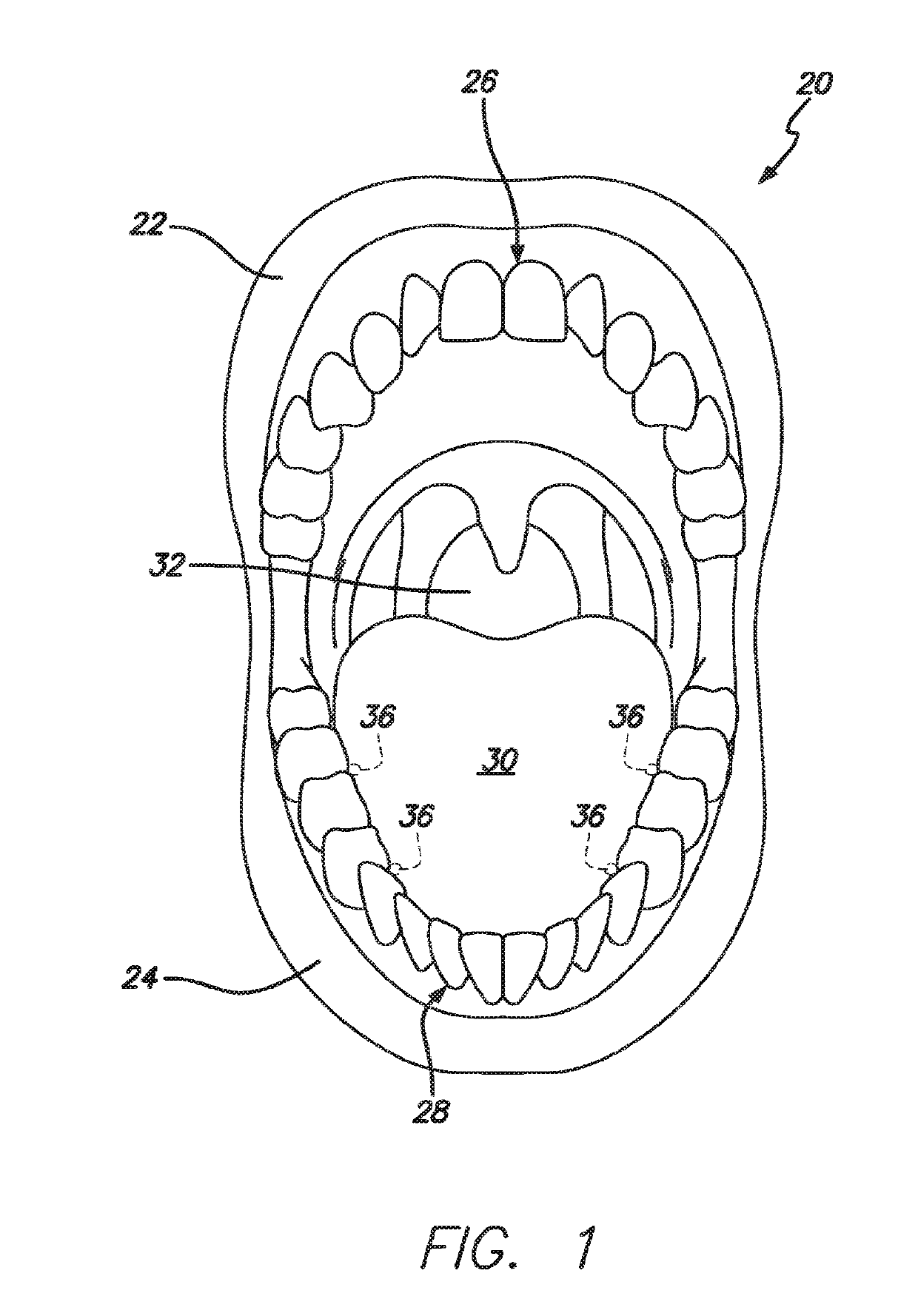
[0022]Accordingly, as depicted in FIG. 1, a user's oral cavity and oropharynx 20 is shown as including upper and lower lips 22 and 24, upper (maxillary) and lower (mandibular) teeth 26 and 28, a tongue 30, and an airway or air passage 32, among other parts.

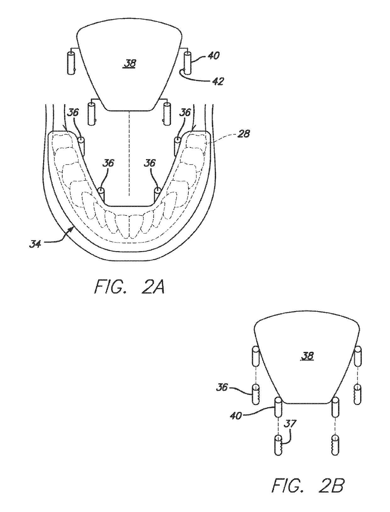
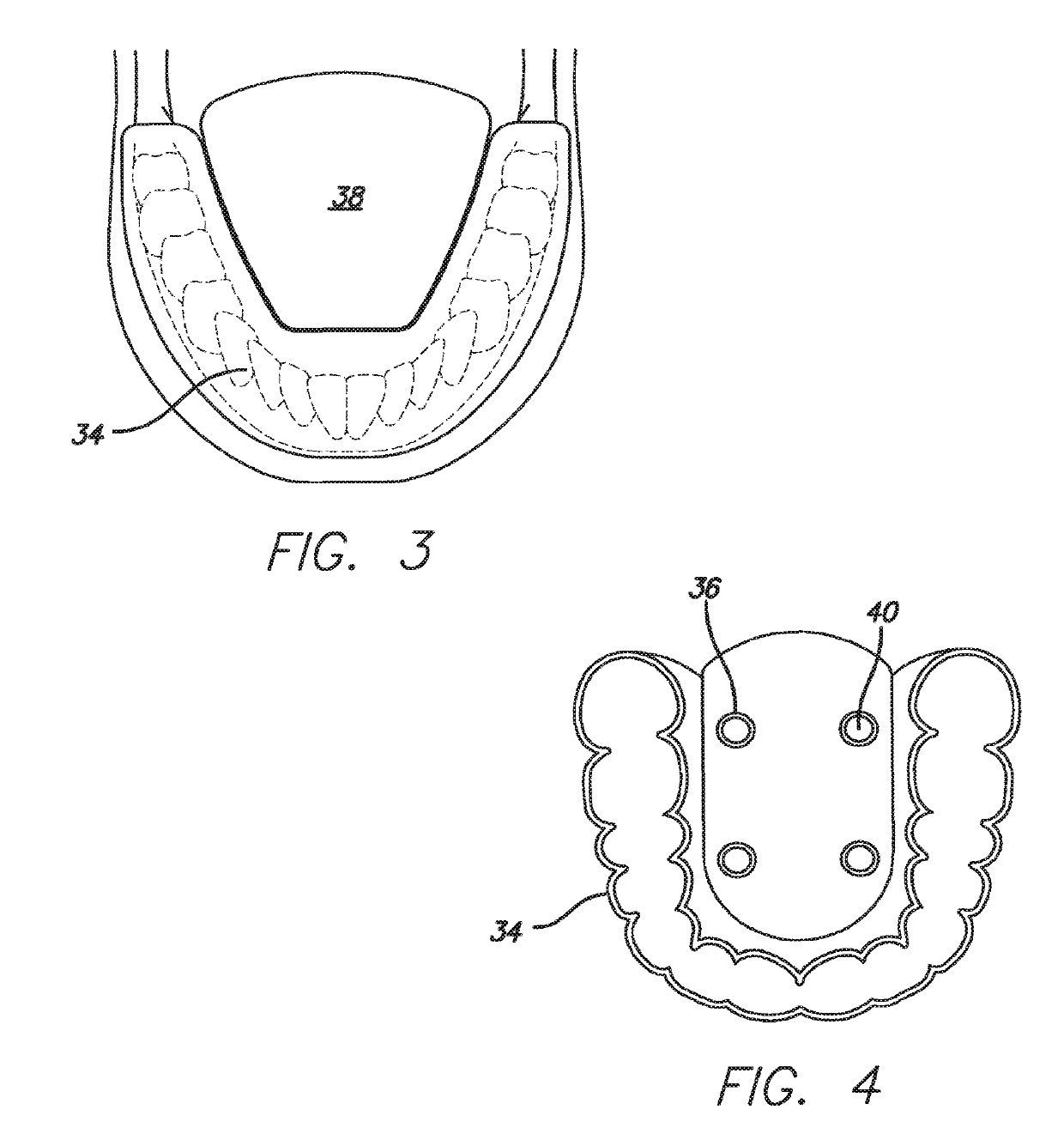
[0023]Referring to FIGS. 2a and 2b, the apparatus and a method relating to sleep apnea, as embodied in the present invention, is embodied as a bite block 34 which is configured and molded to encompass lower teeth 28. Attached to bite block 34 are a plurality of receiving cylinders 36, preferably four in number, appropriately positioned within the interior of the bite block. Each receiving cylinder includes a plurality of holes 37 extending along its length. A tongue restrictor 38 is positioned above the bite block and has a plurality of connecting rods 40, preferably four in number, appropriately placed about the exterior of the tongue restrictor and aligned with receiving cylinders 36. Tongue 30 is disposed to reside under tongue...


PUM


Abstract

The dental sleep apnea device and method utilizes a bite block (34) and a clear plastic tongue restrictor (38, 138) which is adjustable on the bite block by a coupling between a connecting rod with a spring-biased button assembly (46) that is capable of accommodating differing users' tongues (30). Sleep apnea is avoided by preventing the tongue from falling back during sleep and blocking the airway, and avoiding the creation of a diminished air supply, which can result a cessation of breathing while, at the same time, permitting the tongue to slide in an otherwise normal fashion. The tongue is thus not trapped in an uncomfortable manner and, therefore, during sleep, the patient can swallow because the tongue is allowed to move freely. When the tongue is so freely restricted, the patient will thus be able to rest as required and desired. The tongue restrictor coupling, when provided with swiveling and linear motion, enables the tongue restrictor to have a standard and fixed configuration which is couplable with any specifically formed bite block for multiple patients having differently sized mandibulars (lower jaws).

Description

CROSS-REFERENCE TO RELATED APPLICATION[0001]This application claims the benefit of U.S. Provisional Application No. 61 / 764,535, filed 14 Feb. 2013.REFERENCE REGARDING FEDERAL SPONSORSHIP[0002]Not ApplicableREFERENCE TO MICROFICHE APPENDIX[0003]Not ApplicableBACKGROUND OF THE INVENTION1. Field of the Invention[0004]The present invention relates to an apparatus and a method relating to sleep apnea and, in particular, to improvements in such apparatus and method in which a person's tongue is prevented from falling back into the airway during sleep, by restricting the tongue's ability to do so, but not to impede otherwise movement of the tongue, that is, to permit the tongue to move freely as normal, with the exception of its falling backward, so as to enable as little disturbance to the person's sleep.2. Description of Related Art and Other Considerations[0005]Known apparati and methods physically hold the tongue captive, e.g., by using a vacuum or a tongue tip holder device that holds...

Claims


Application Information

Patent Timeline
Patent Type & Authority Applications(United States)
IPC IPC(8): A61F5/56
CPCA61F5/566A61F2005/563
Inventor KANER, ALBERT H.
Owner KANER ALBERT H
Why Eureka
Try Eureka