Device and Method for Axis Marking

a marking device and axis technology, applied in the field of eye surgery, can solve the problems of significant potential errors in significant loss of corrective power to the patient, and significant affecting the alignment of the implanted lens, etc., and achieve the effect of high accuracy

Inactive Publication Date: 2019-06-06
SUNALP MURAD
View PDF3 Cites 2 Cited by
  • Summary
  • Abstract
  • Description
  • Claims
  • Application Information

AI Technical Summary

Benefits of technology

[0011]It is an object of this invention, to provide a method for imparting indicia to the cornea in a highly accurate fashion, which is not erasable, but which will naturally disappear within days.

Problems solved by technology

Where there exists even a minor misalignment of the positioning of the lens within the eye, a significant portion of the corrective power is lost to the patient.
Conventionally, marking the eye of a patient to provide a visually discernable position reference is a significant potential source of error.
Should the mark be misplaced, or as can easily occur where ink markings are used, should the mark disappear during surgery, resulting alignment of the implanted lens can be significantly impacted.
While a number of high tech means of alignment have been developed which provide computer aided marking through a computer generated targeting, such is expensive to implement and not always accurate.
However, markers vary on width and can, thus, impart overly large markings on the eye which can be many degrees in width.
Such markings yield diminished accuracy of the subsequent lens alignment since they are many degrees in width and placed on the eye freehand, which in itself can be inaccurate by a number of degrees.
Further, using a felt tip marker to impart ink to the eye can yield markings of highly variable duration on the eye itself.
Should the imparted markings somehow disappear or smudge during the surgical procedure, a significant misalignment of the implanted lens can occur, thereby diminishing the visual correction to the patient.
Various limitations of the related art will become apparent to those skilled in the art upon a reading and understanding of the specification below and the accompanying drawings.

Method used


Image

  • Device and Method for Axis Marking
  • Device and Method for Axis Marking
  • Device and Method for Axis Marking

Examples


Embodiment Construction

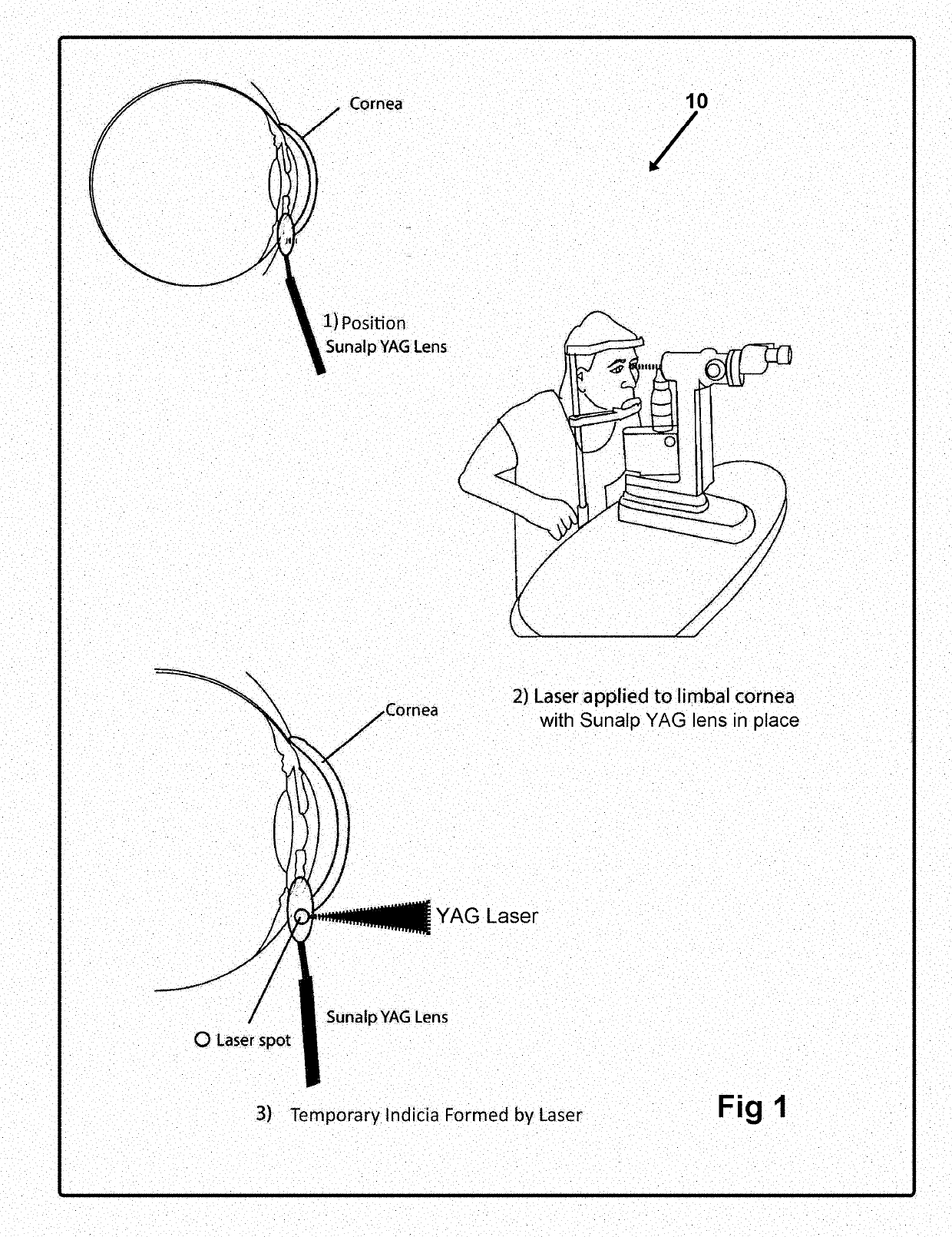
[0059]Now referring to drawings in FIGS. 1-13, wherein similar components are identified by like reference numerals, there is seen in FIG. 1, the steps in the method 10 herein disclosed for imparting markings into the cornea between 40-450 microns below the surface thereof. The formed temporary markings are subsequently employable for implanted lens orientation and will not move or erase for substantially two days.

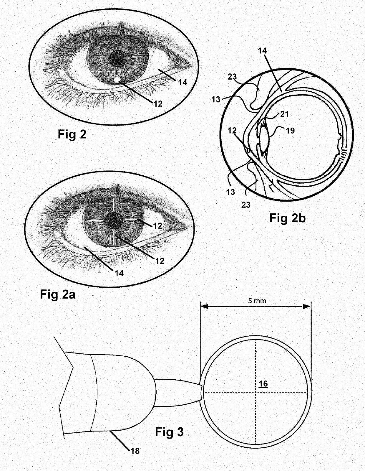
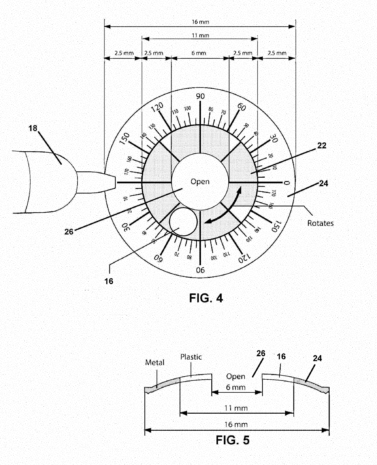
[0060]In all modes of the method, at least one lens 16 for targeting the laser is positioned adjacent or upon the eye of the patient in a position where a marking 12 is desired. Once so positioned, in a next step, a YAG laser or other directed energy device is communicated through the targeting lens 16 and is focused to a focal point between 40 and 450 microns, below the surface of the cornea, within the corneal layer of the eye. The laser communicating through the lens 16 forms the markings 12 at the depth of and in a position within the cornea, determined by the lens 16 ...


PUM


Abstract

A method and device is provided for forming discernable markings within the cornea of an eye. Using a lens having a focal length to communicate and focus a laser to a focal point within the corneal layer of an eye, temporary markings can be formed within the corneal layer below its exterior surface. So formed the markings will remain for a number of days and provide the surgeon the ability to use the markings during eye surgery.

Description

[0001]This application claims priority to U.S. Provisional Patent Application Ser. No. 62 / 209,734, filed on Aug. 25, 2015, which is incorporated herein in its entirety by this reference thereto.FIELD OF THE INVENTION[0002]This invention relates in general to eye surgery. More particularly, it relates to a method generating a temporary visually-discernable mark on the eye of a patient, and devices adapted to impart such indicia or markings. The method and apparatus is employable to impart temporary indicia into the cornea for use in subsequent intraocular lens alignment and orientation during an implant thereof in the eye of a patient.BACKGROUND OF THE INVENTION[0003]As lens implants for eyes, particularly astigmatic keratotomy and toric intraocular lens implantations, become more widespread, the accurate alignment of the implanted lens as positioned within the eye is a significant concern. Where there exists even a minor misalignment of the positioning of the lens within the eye, a ...

Claims


Application Information

Patent Timeline
Patent Type & Authority Applications(United States)
IPC IPC(8): A61F9/013A61F9/008
CPCA61F9/0136A61F9/008
Inventor SUNALP, MURAD
Owner SUNALP MURAD
Why Eureka
Try Eureka