Processing center

a processing center and processing technology, applied in the field of processing centers, can solve the problems of limited movement of such tool carrier systems, and series of processing operations can, if at all, only be carried out with considerable expenditur

Inactive Publication Date: 2003-04-10
WALDRICH SIEGEN WERKZEUGMASCHEN
View PDF13 Cites 5 Cited by
  • Summary
  • Abstract
  • Description
  • Claims
  • Application Information

AI Technical Summary

Problems solved by technology

However, the movements of such tool carrier systems are limited due to the risk of collisions with the workpieces.
Due to the interfering contours of the processing units, a series of processing operations can, if at all, only be carried out with considerable expenditure.

Method used


Image

  • Processing center
  • Processing center
  • Processing center

Examples


Embodiment Construction

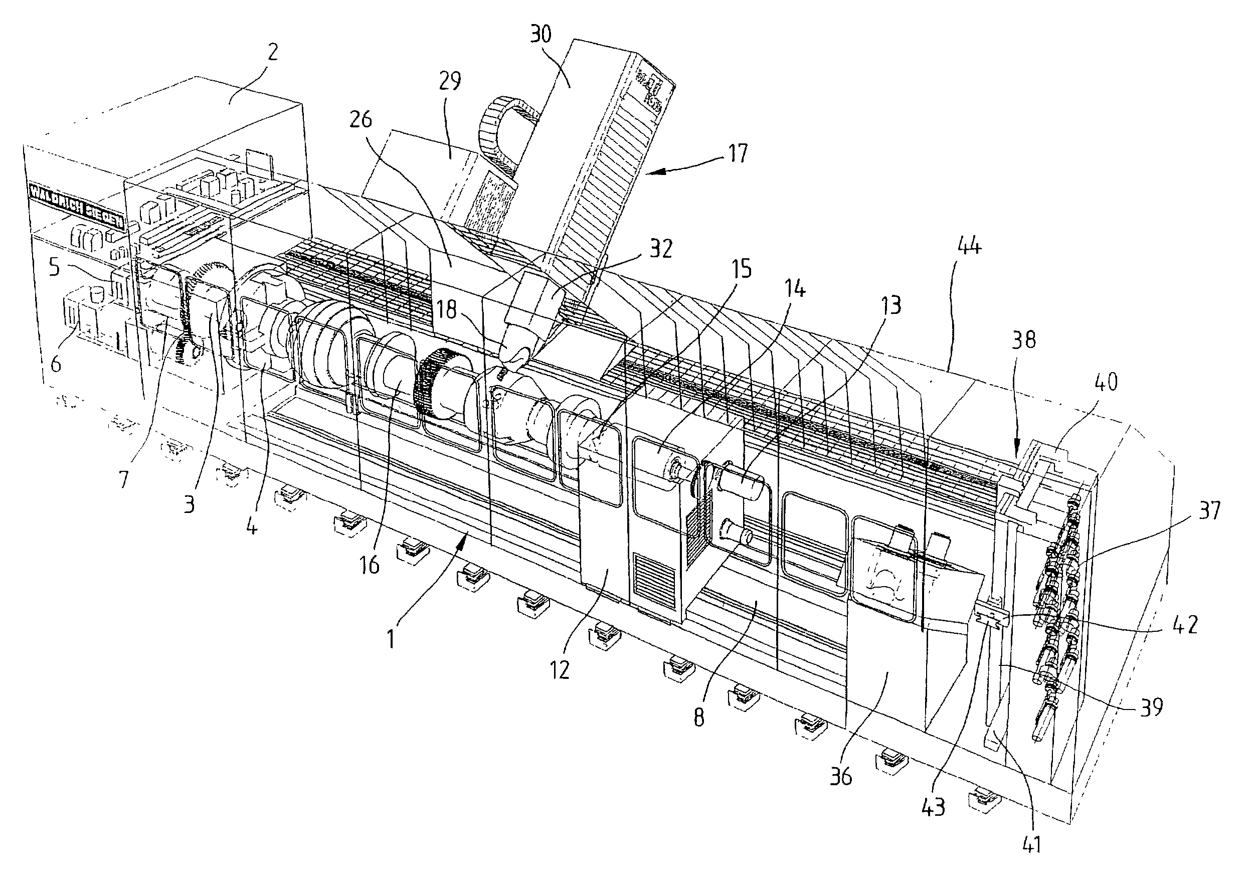
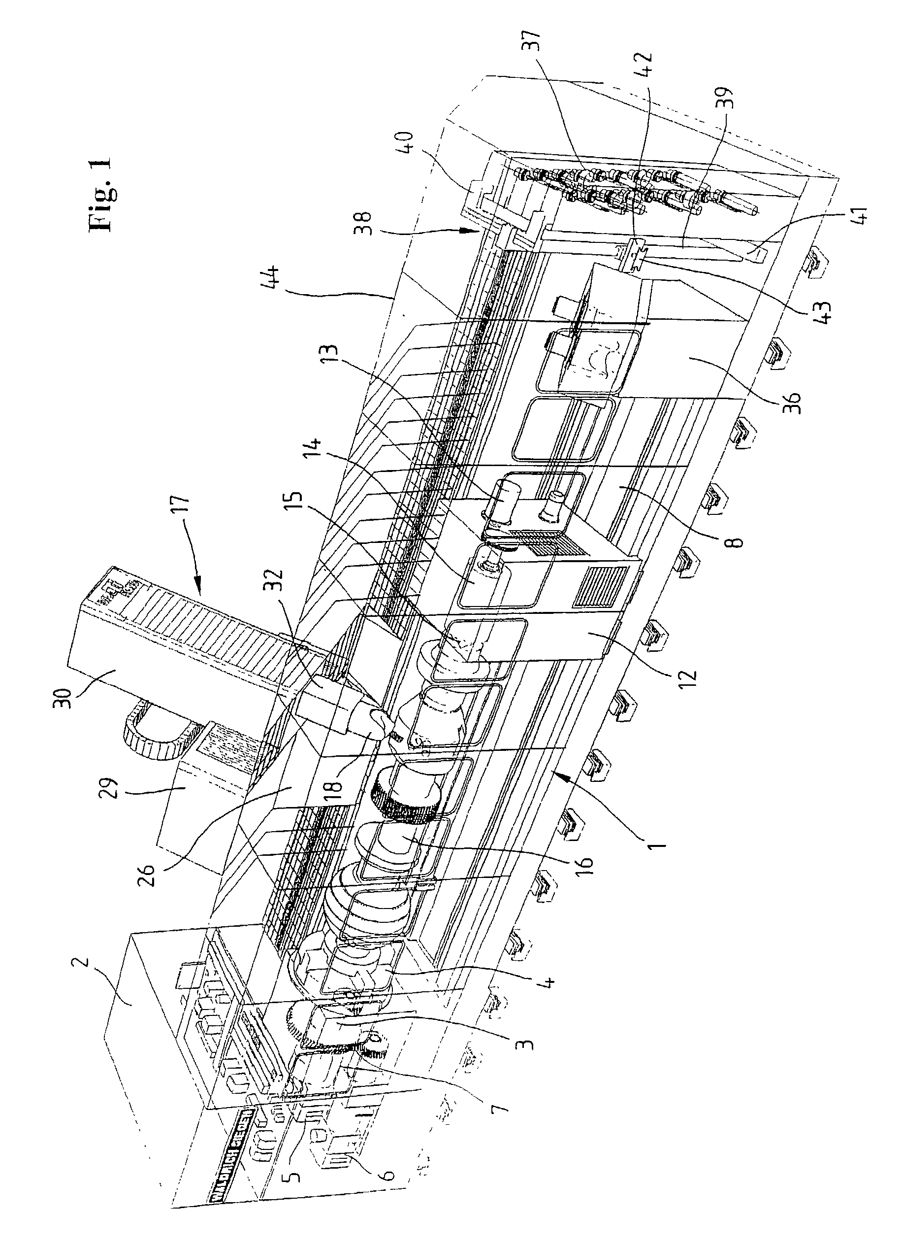
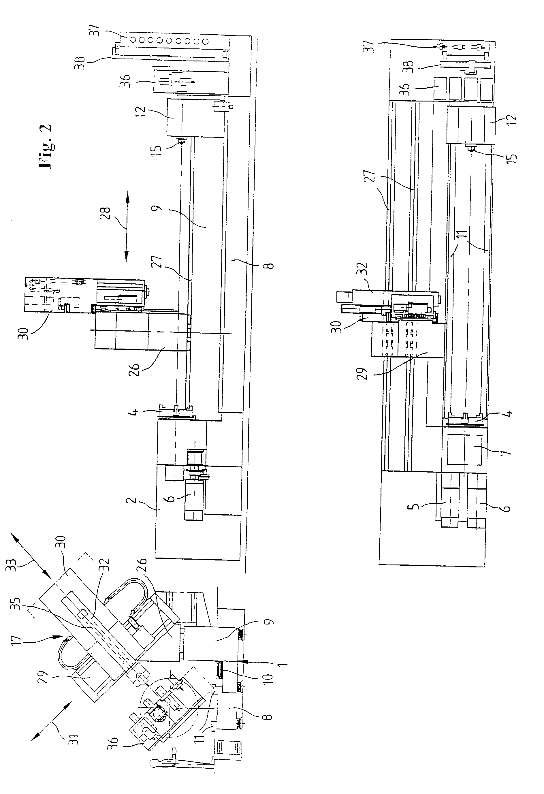
[0021] The processing center for round workpieces which is schematically illustrated in FIGS. 1 and 2 contains a machine bed 1 and a headstock 2, in which a horizontal workpiece driving spindle 3 with a workpiece clamping device 4 in the form of an end face chuck is rotatably supported. The drive of the workpiece driving spindle 3 is realized with the aid of one or two parallel driving motors 5 and 6, namely via one respective switchable two-stage planetary gear 7 that ensures a high operational reliability and an optimally quiet operation. The drive can be optimally adapted to the machine by providing the machine with one or two driving motors 5 and 6 in the form of rotary current motors. The drive is designed in such a way that it can be used as a rotary drive, as well as a position drive and a circular milling drive.

[0022] FIG. 2, in particular, shows that the machine bed 1 is realized in the form of a one-part stepped bed with a front bed section 8 and an elevated rear bed secti...


PUM

PropertyMeasurementUnit
angleaaaaaaaaaa
angleaaaaaaaaaa
dynamic rigidityaaaaaaaaaa

Abstract

A processing center for round workpieces with a machine bed, a horizontal main driving spindle with a workpiece chuck which is rotationally supported on the machine bed in a lateral headstock and rotationally driven by a drive, a tailstock that is arranged on the machine bed and a support that is displaceably arranged on the machine bed. The support contains a table saddle that can be displaced on the machine bed and an upper headstock that is obliquely arranged on the table saddle and contains a carrier that can be displaced along the longitudinal axis of the upper headstock. Exchangeable processing units for carrying out different processing technologies can be inserted into the displaceable carrier.

Description

[0001] 1. Field of the Invention[0002] The invention pertains to a processing center for round workpieces,[0003] 2. Prior Art[0004] When manufacturing essentially rotationally symmetrical workpieces, it is common practice to utilize lathes in which the rotational cutting movement is carried out by the workpiece and the advance movement is carried out by the tool and / or vice versa. In numerically controlled automatic lathes, so-called inclined-bed machines are frequently utilized, wherein the support that carries the tools is arranged on an inclined guide surface of the machine bed. Tool carrier systems that, for example, are realized in the form of star-type modules, turret modules or drilling and milling modules are provided for carrying out various processing steps with different tools. Smaller processing units for carrying out certain milling or drilling processes can also be used in carrier systems of this type. However, the movements of such tool carrier systems are limited due...

Claims


Application Information

Patent Timeline
Patent Type & Authority Applications(United States)
IPC IPC(8): B23B11/00B23Q3/157B23Q1/01B23Q1/62B23Q3/155
CPCB23Q1/015B23Q1/626B23Q3/155Y10T483/1705Y10T483/1748Y10T483/1702Y10T29/5114
Inventor BINDER, ROLFDUERLER, FRITZ
Owner WALDRICH SIEGEN WERKZEUGMASCHEN
Why Eureka
Try Eureka