Data transmission rate control using a transmission control scheme suitable for subbands forming an entire band

Inactive Publication Date: 2001-05-01
RAKUTEN INC
View PDF9 Cites 5 Cited by
  • Summary
  • Abstract
  • Description
  • Claims
  • Application Information

AI Technical Summary

Benefits of technology

According to the data transmission rate control method and system in accordance with the present invention, the entire band is divided into a plurality of subbands so that a transmission control scheme suitable for each subband is used. Thus, the data can be transmitted over each channel by a control scheme appropriate for the transmission bandwidth of that channel. This makes it possible for each channel to control data transmission in a highly accurate fashion, even if the channels range over a wide transmission band.

Problems solved by technology

The foregoing control schemes, however, present the following problems.
First, since the cell-based minimum cell interval control scheme controls the transmission of cells based on the cell period, it has a problem in that gaps or intervals between controllable values become rough at high rates (particularly, in a range close to the peak rate).
In addition, since the cell-based minimum cell interval control scheme checks each channel in time division mode, its accuracy degrades with the increasing number of channels.
For example, assume that the number of channels is 1024, that the check is carried out one channel per clock period, and that one cell period is 53 clock periods; it takes about 20 cell periods to complete all of the cells, which may cause time errors in the transmission control.
Second, although the clock-based minimum cell interval control scheme can solve the controllable gap problem of the cell-based minimum cell interval control scheme, it presents a new problem in that increase in circuit scale is unavoidable as compared with the cell-based minimum cell interval control scheme.
Finally, the sliding window control scheme has a problem in that the width of the shift register increases as the minimum value of the controllable value decreases.
Therefore, when the transmission rate of a particular channel is 0.01% of the peak rate, flip-flops of 320 kilobits are required, which presents a problem in that it is difficult to implement such a system in hardware.
Moreover, although it is possible for the cell-based minimum cell interval control scheme or clock-based minimum cell interval control scheme to perform transmission always at a fixed rate independently of the bandwidth because the transmission interval is checked between the previous cell and the current cell, the sliding window control scheme, which determines transmission according to the number of cells in the time window, and hence requires a wider time window as the bandwidth of the channel decreases, has a problem in that the fluctuations of the cells in the time window increase with decreasing bandwidth.

Method used


Image

  • Data transmission rate control using a transmission control scheme suitable for subbands forming an entire band
  • Data transmission rate control using a transmission control scheme suitable for subbands forming an entire band
  • Data transmission rate control using a transmission control scheme suitable for subbands forming an entire band

Examples


first embodiment

the data transmission rate control system in accordance with the present invention, which will now be described, is applied to a cell rate control system in a cell transfer type of telecommunications system. This embodiment is adapted to divide the controlled band into an upper band and a lower band so that the control scheme is changed in accordance with the band in such a manner that the transmission timing of input cells belonging to the upper band is controlled by the clock-based minimum cell interval control scheme, while that of input cells belonging to the lower band is controlled by the cell-based minimum cell interval control scheme.

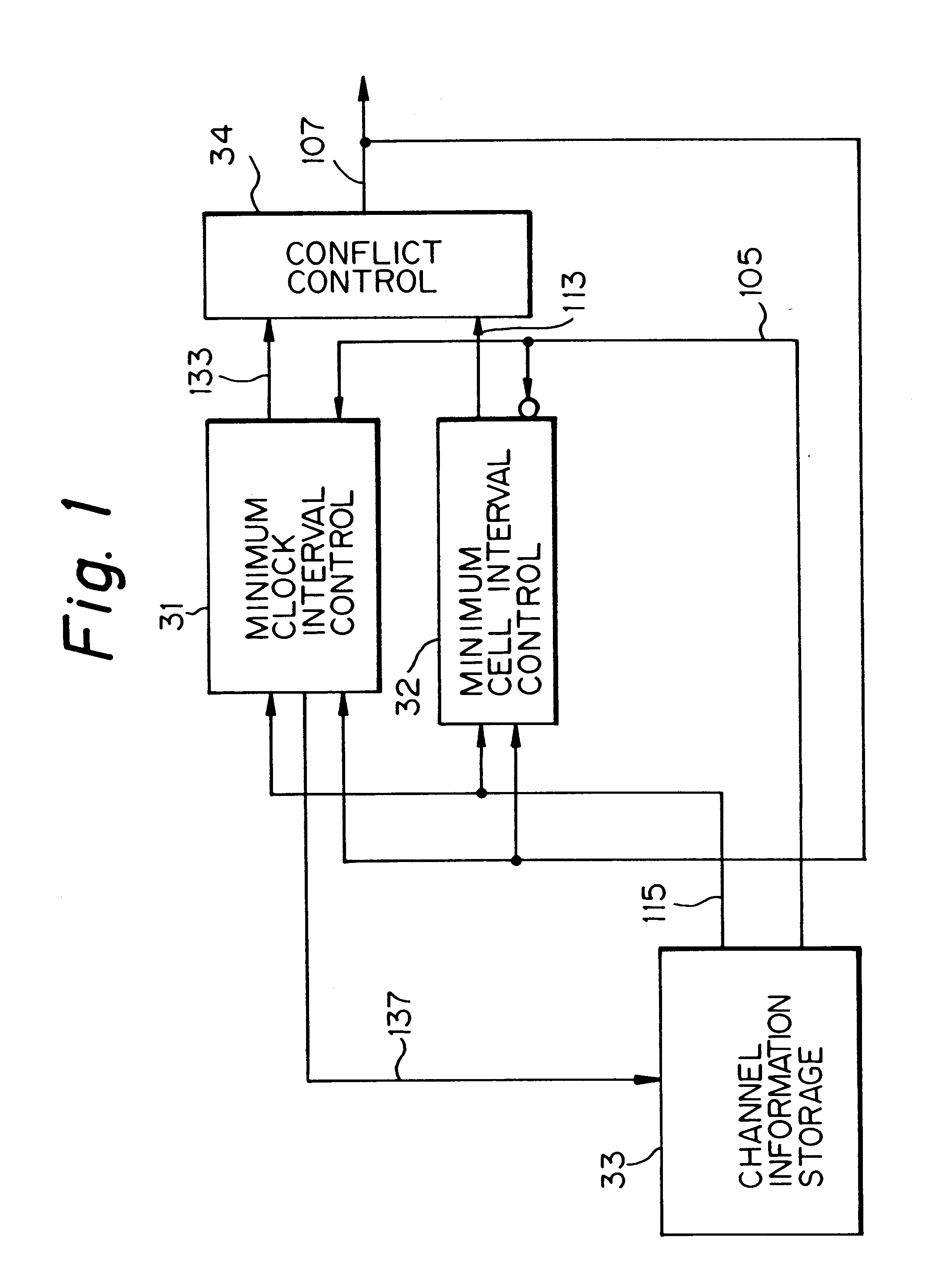
With reference to FIG. 1, which shows in a block diagram the cell rate control system associated with the first embodiment, the cell rate control system generally includes four functional blocks: a clock-based minimum cell interval control 31; a cell-based minimum cell interval control 32; a channel information memory 33; and a conflict control ...

embodiment 2

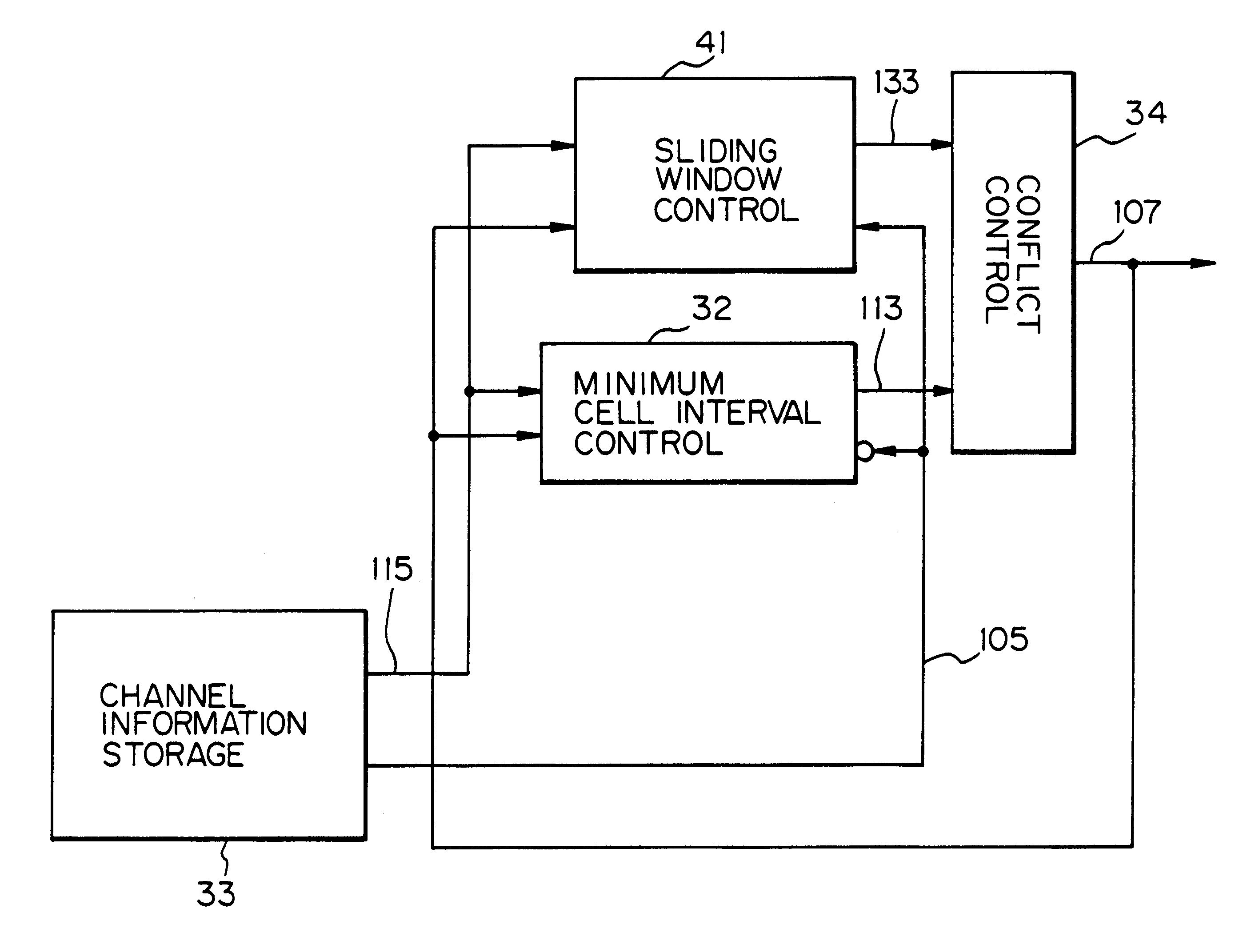
An alternative, or second, embodiment of a data transmission rate control unit in accordance with the present invention will be described referring to the drawings. In this embodiment, the data transmission rate control unit is applied to the cell rate control unit in a cell transfer communications system. In the cell rate control unit in accordance with the second embodiment, the control band is also divided into the upper and lower bands, to which different control schemes are applied. In the instant embodiment, however, the sliding window control scheme is assigned to the upper band with a wider control bandwidth, and the cell-based minimum cell interval control scheme is assigned to the lower band with a narrower bandwidth, thereby making good use of the advantages of the respective control methods.

This embodiment is described with reference to FIG. 5, which shows in a block diagram the cell rate control unit relating to the second embodiment. The cell rate control unit includes...


PUM


Abstract

A data transmission rate control method in which a transmission control scheme used for data transmission over each channel is switched depending on a subband to which a proper transmission rate of the channel belongs, the subband being prepared by dividing an entire band by one or more boundaries. This makes it possible to solve a problem in conventional systems of variations in accuracy due to the bandwidth, and an increase in the circuit scale, when the a cell rate to be controlled ranges over wide bandwidth.

Description

1. Field of the InventionThe present invention relates to a data transmission rate control method and system applicable to cell transfer switches such as ATM (Asynchronous Transfer Mode) switches, ATM routers, ATM bridges, or other telecommunications equipment.2. Description of the Background ArtToday, the following three methods are predominantly used for controlling the transmission rate of a fixed length of data (referred to as a cell below): the two minimum intercell gap, or cell interval, control schemes or methods, including a cell period based scheme and a clock period based scheme; and the sliding window control scheme. To distinguish the two minimum cell interval control schemes from each other hereinbelow, the cell period based minimum cell interval control scheme is referred to as a cell-based minimum intercell gap control scheme, while the clock period based minimum cell interval control scheme is referred to as a clock-based minimum cell interval control scheme.First, t...

Claims


Application Information

Patent Timeline
IPC IPC(8): H04Q11/04H04L12/56H04L47/27H04Q3/00
CPCH04Q11/0478H04L2012/5672H04L2012/5679
Inventor YAJIMA, YOSHIYUKITANAKA, MAKOTO
Owner RAKUTEN INC
Why Eureka
Try Eureka