Unlock instant, AI-driven research and patent intelligence for your innovation.
Image forming apparatus
Active Publication Date: 2019-06-06
CANON KK
View PDF0 Cites 0 Cited by
Summary
Abstract
Description
Claims
Application Information
AI Technical Summary
This helps you quickly interpret patents by identifying the three key elements:
Problems solved by technology
Method used
Benefits of technology
Benefits of technology
[0012]A principal object of the present invention is to provide an image forming apparatus capable of forming a high-quality image by equalizing magnification differential values
Problems solved by technology
Here, in the conventional optical constitution using the fθ lens, the magnification correction in one scanning is made with a value of ±3%,
Method used
Image
Click on the blue label to locate the original text in one second.
Reading with bidirectional positioning of images and text.
Examples
Example
First Embodiment
(Image Forming Apparatus)
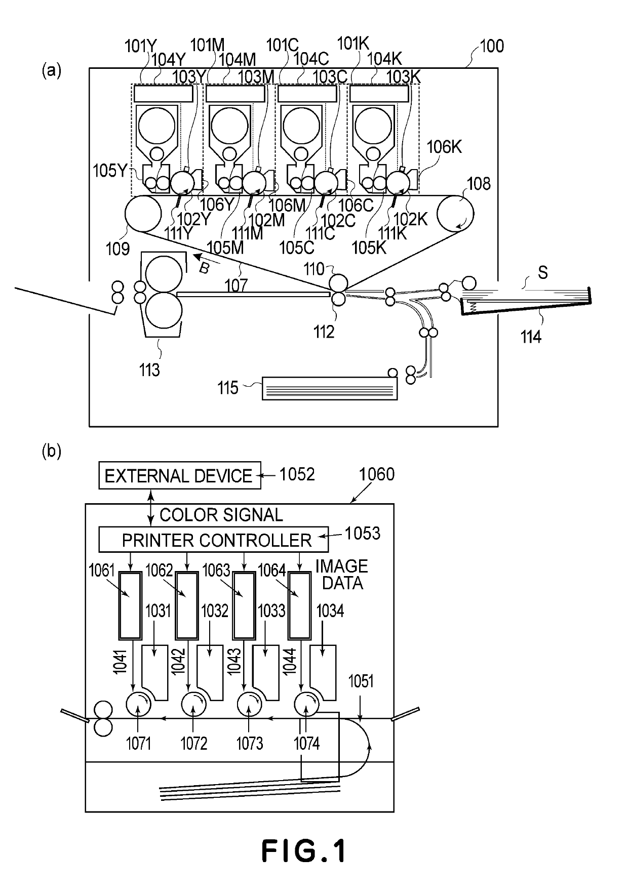
[0032]Part (a) of FIG. 1 shows a structure of a main assembly of a digital copying machine which is an example of an image forming apparatus according to an embodiment of the present invention. Specifically, part (a) of FIG. 1 is a schematic sectional view of a digital full-color printer (color image forming apparatus) for forming an image with toners of a plurality of colors. An image forming apparatus 100 includes four image forming portions 101Y, 101M, 101C and 101K for forming images color by color. Here, Y, M, C and K represent yellow, magenta, cyan and black, respectively. The image forming portions 101Y, 101M, 101C and 101K carry out image formation with toners of yellow, magenta, cyan and black, respectively.
[0033]The image forming portions 101Y, 101M, 101C and 101K include rotatable photosensitive drums 102Y, 102M, 101C and 101K, respectively.
[0034]At peripheries of the photosensitive drums 102Y, 102M, 102C and 102K, charging devices...
Example
Modified Embodiment 1
[0104]In the above-described embodiment, on the basis of the second magnification data in the respective segments, the pixel magnifications at the pixel positions in the segments are calculated using the curve functions depending on the respective segments, but the present invention is not limited thereto. For example, the pixel magnifications at the respective pixel positions may also be calculated using a single curve function with all the data of M0 to M31 as the second magnification data in the segments.
Example
Modified Embodiment 2
[0105]Further, in the above-described embodiment, as the curve function, the quadratic function was used, but ternary or more functions may also be used. Further, the number of divided region (segments) is not limited to 32.
[0106]According to the present invention, it is possible to provide an image forming apparatus in which even in a constitution with a simple fθ lens and a constitution with no fθ lens, a high-quality image is capable of being formed by equalizing magnification differential values at a boundary of adjacent divided regions with respect to a scanning direction of a light beam.
[0107]While the present invention has been described with reference to exemplary embodiments, it is to be understood that the invention is not limited to the disclosed exemplary embodiments. The scope of the following claims is to be accorded the broadest interpretation so as to encompass all such modifications and equivalent structures and functions.
[0108]This application ...
PUM
Abstract
An image forming apparatus includes a photosensitive member, a light source, a deflecting unit, a storing unit, a correcting unit, and a light source driving portion. Magnification correction data is determined using a quadratic function of a variable representing a scanning position with respect to a scanning direction. Coefficients of two quadratic functions corresponding to adjacent two regions included in a plurality of scanning regions are set so that a differential value calculated at the variable corresponding to a boundary of the two regions by a differential of the quadratic function for one region and a differential value calculated at the variable corresponding to the boundary of the two regions by a differential of the quadratic function for the other region are equal to each other.
Description
[0001]FIELD OF THE INVENTION AND RELATED ART[0002]The present invention relates to an image forming apparatus and relates to magnification correction in optical scanning suitable for the image forming apparatus of an electrophotographic type, such as a copying machine or a printer, for example.[0003]Conventionally, in the image forming apparatus of the electrophotographic type, a photosensitive drum surface is electrically charged by a charging device uniformly, and an electrostatic latent image is formed using an exposure device for scanning the photosensitive drum surface with laser light, and then the electrostatic latent image is visualized as a toner image by depositing toner on thereon by a developing device. Then, the toner image is transferred onto a recording material (medium) such as paper by a transfer device and is fixed on the recording material by a fixing device.[0004]In such a constitution, in the exposure device, the photosensitive drum surface is two-dimensionally ...
Claims
Application Information
Patent Timeline
Application Date:The date an application was filed.
Publication Date:The date a patent or application was officially published.
First Publication Date:The earliest publication date of a patent with the same application number.
Issue Date:Publication date of the patent grant document.
PCT Entry Date:The Entry date of PCT National Phase.
Estimated Expiry Date:The statutory expiry date of a patent right according to the Patent Law, and it is the longest term of protection that the patent right can achieve without the termination of the patent right due to other reasons(Term extension factor has been taken into account ).
Invalid Date:Actual expiry date is based on effective date or publication date of legal transaction data of invalid patent.
