
Local thermal control of wireless access points

a wireless access point and thermal control technology, applied in the field of wireless networking systems and methods, can solve the problems of increasing the size, complexity, and cost of the product, reducing the maximum possible performance of the wireless router, and reducing the power of the transmitter, so as to reduce the load, reduce the traffic load, and reduce the effect of power

Active Publication Date: 2019-06-06
PLUME DESIGN INC
View PDF1 Cites 7 Cited by
  • Summary
  • Abstract
  • Description
  • Claims
  • Application Information

AI Technical Summary

Benefits of technology

The patent describes a method for controlling the temperature of an access point in a cloud-based network. The method involves periodically measuring the temperature of the access point and adjusting the operating conditions of the radio chips in the access point to reduce the temperature if it exceeds a certain threshold. This can include reducing the number of radio chips in use, reducing the power of the transmitter, or controlling the duty cycle of the transmitter. The method can also involve optimizing the network configuration to compensate for the adjustments made to the access point's operating conditions. The technical effect of this patent is to improve the thermal performance of the access point and enhance the overall performance of the network.

Problems solved by technology

Disadvantageously, compact designs of powerful access points, wireless routers, etc., containing multiple radios each with numerous Radio Frequency (RF) chains, can result in the wireless router dissipating more heat than can be quickly removed from it.
However, both of these solutions reduce the maximum possible performance of the wireless router.
Alternatively, some wireless routers are designed with larger surface area, and include heat sinks, venting holes, fans, and other additions, increasing the size, complexity, and cost of the product.
Small size, no external heat sinks, no venting holes, quiet operation without fans, all make the product more attractive, but they make keeping the product cool more difficult.
The result is the potential for the APs to overheat, degrading performance and product lifetime.

Method used


Image

  • Local thermal control of wireless access points
  • Local thermal control of wireless access points
  • Local thermal control of wireless access points

Examples


Embodiment Construction

[0031]In various exemplary embodiments, the present disclosure relates to thermal management of wireless access points including local thermal management, cloud-based thermal management, and thermal management based on optimization and operation in a distributed Wi-Fi network. The objective of the present disclosure is for thermal management in access points allowing small form-factors and aesthetic designs, preventing overheating and without requiring reduced performance or reduced hardware. Generally, the systems and methods detect when access points are nearing overheating and alter their operation so as to minimize the reduction of performance in the network while reducing power consumption.

Distributed Wi-Fi System

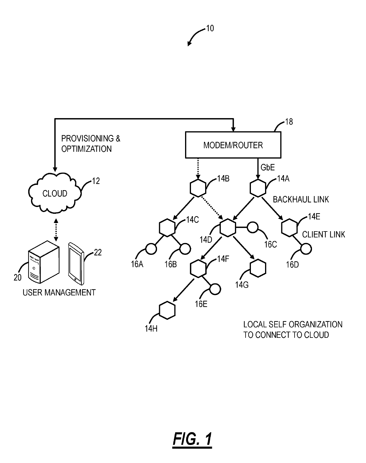
[0032]FIG. 1 is a network diagram of a distributed Wi-Fi system 10 with cloud-based 12 control. The distributed Wi-Fi system 10 can operate in accordance with the IEEE 802.11 protocols and variations thereof. The distributed Wi-Fi system 10 includes a plurality of acce...


PUM


Abstract

Systems and methods of local thermal control of an access point include determining temperature associated with the access point including one or more radio chips operating therein; responsive to the temperature exceeding a first threshold, performing one or more thermal mitigation techniques to modify operating conditions of the one or more radio chips; and, responsive to the temperature being lower than a second threshold, reverting back the one or more thermal mitigation techniques.

Description

FIELD OF THE DISCLOSURE[0001]The present disclosure generally relates to wireless networking systems and methods. More particularly, the present disclosure relates to thermal management of wireless access points including local thermal management, cloud-based thermal management, and thermal management based on optimization and operation in a distributed Wi-Fi network.BACKGROUND OF THE DISCLOSURE[0002]In Wi-Fi networks and the like, the trend is deploying smaller form-factor devices that have compelling aesthetic designs. This is especially important in mesh and distributed Wi-Fi systems which require numerous access points deployed throughout a location. Disadvantageously, compact designs of powerful access points, wireless routers, etc., containing multiple radios each with numerous Radio Frequency (RF) chains, can result in the wireless router dissipating more heat than can be quickly removed from it. Typical solutions today are to limit the number of radio chains built into a dev...

Claims


Application Information

Patent Timeline
Patent Type & Authority Applications(United States)
IPC IPC(8): G06F1/20H04W52/38
CPCG06F1/206H04W52/38H04W88/08H04B7/0413H04W84/12G01K13/00G01K1/024G01K3/005H04W52/367H04B17/318
Inventor MCFARLAND, WILLIAMMALKIN, YOSEPHCHANG, RICHARDHANLEY, PATRICK
Owner PLUME DESIGN INC
Learn More