Selective-access data-center racks

Active Publication Date: 2019-06-06
VAPOR IO INC
View PDF0 Cites 17 Cited by
  • Summary
  • Abstract
  • Description
  • Claims
  • Application Information

AI Technical Summary

Benefits of technology

[0005]Some aspects include an apparatus, including: a rack assembly comprising a plurality of racks coupled to one another, wherein: respective racks among the plurality of racks are configured to hold a plurality of rack-mounted computing devices arrayed in a first direction; the plurality of racks are arrayed in one or more directions orthogonal to the first direction for respective racks, with respective racks positioned side-by-side; a rack-assembly enclosure, wherein: the rack-assembly enclosure is coupled to the rack assembly with: at least one degree of freedom of relative movement between the rack-assembly enclosure and the rack assembly, and fewer than three degrees of freedom of relative movement between the rack-assembly enclosure and the rack assembly; the rack-assembly enclosure comprises a barrier configured to block access to an inaccessible subset of the plurality of racks; the rack-assembly enclosure comprises an opening in the barrier configured to permit access to at least part of an accessible subset of the plurality of racks, the accessible subset and the inaccessible subsets being disjoint sets; the rack assembly and rack-assembly enclosure are configured to determine which of the plurality of racks are in the inaccessible subset and which of the plurality of racks are in the accessible subset responsive to the at least one degree of freedom of relative movement between the rack-assembly enclosure and the rack assembly, such that relative movement of the rack assembly and rack-assembly enclosure selectively provides physical access to a technician to different rack unit portions of the rack assembly; and an actuator mechanically coupled to the rack assembly or the rack-assembly enclosure, the actuator being configured to actuate relative movement between the rack assembly and the rack-assembly enclosure in at least one of the one or more degrees of freedom.
[0006]Some aspects include a process, including: receiving, with one or more processors, a command requesting access to a subset of racks in a rack assembly; accessing, with one or more processors, a tenant account among a plurality of tenant accounts of tenants having computing devices in the rack assembly; determining, with one or more processors, based on the tenant account, that the request is authorized; and in response to the determination, moving the rack assembly relative to a rack enclosure with an actuator and thereby changing which of a plural

Problems solved by technology

These facilities generally aggregate relatively large amounts of computing power and include relatively complex infrastruct

Method used


Image

  • Selective-access data-center racks
  • Selective-access data-center racks
  • Selective-access data-center racks

Examples


embodiment 1

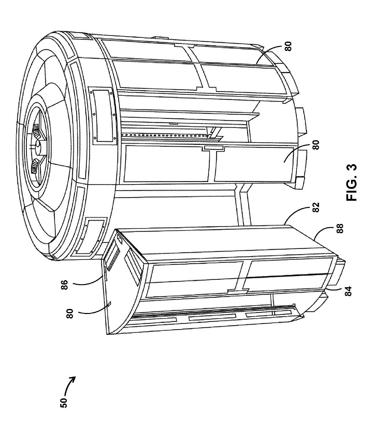
2. The apparatus of embodiment 1, wherein: each respective rack comprises more than four rack units each configured to hold one or more of the rack-mounted computing devices; the rack assembly comprises more than five wedge-shaped racks; the plurality of racks are arrayed in a circular arrangement defining a circular outer perimeter and an interior chamber extending in the first direction; the rack-assembly enclosure comprises one or more walls blocking access to every rack among the plurality of racks in the rack assembly except for those racks aligned with the opening; the opening extends in the first direction at least between a bottom rack unit of the plurality of racks to a top rack unit of the plurality of racks; the opening extends orthogonal to the first direction at least a rack-unit-width of the plurality of racks; the opening extends orthogonal to the first direction less than three rack-unit-widths; the rack-assembly enclosure is coupled to the rack assembly with one and...

embodiment 3

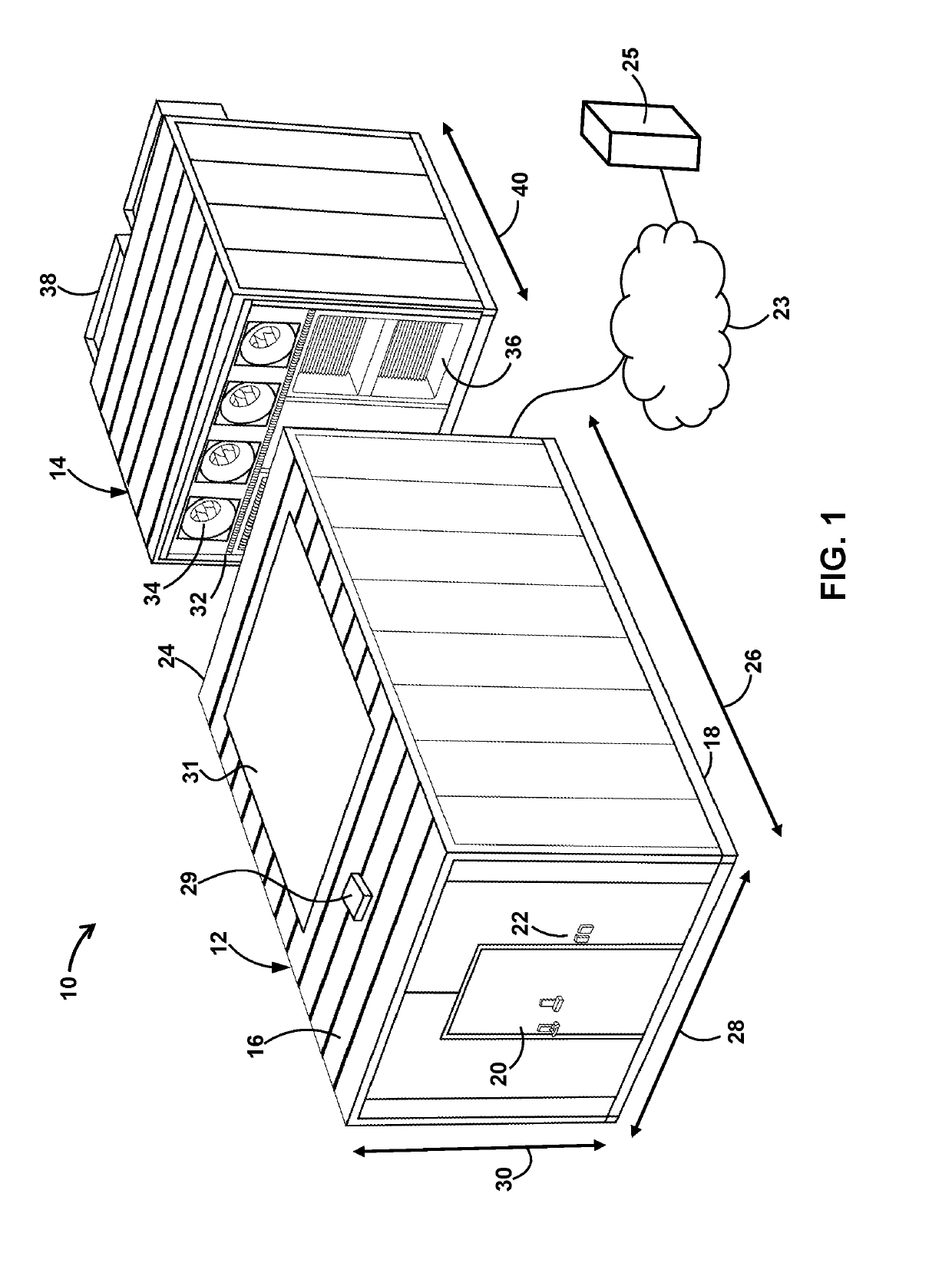
4. The apparatus of embodiment 3, wherein: the building is a modular housing configured to be transported on a truck and protect the rack assembly from weather.

embodiment 4

5. The apparatus of embodiment 4, comprising: a modular cooling unit coupled to the building and configured to: cool the rack mounted computing equipment by removing heat from a cooling fluid circulated through the rack assembly; and be transported on a truck and coupled to the building at an edge-based data center site having fewer than five rack assemblies in five or fewer truck-transportable modular buildings.

6. The apparatus of embodiment 3, comprising: a solar panel coupled to the building; and power conditioning circuitry coupled to the solar panel and configured to provide power from the solar panel to the rack-mounted computing equipment or environmental controls of the building.

7. The apparatus of any one of embodiments 3-6, comprising: a docking station coupled to the building and configured to dock with a drone and recharge the drone while the drone is docked.

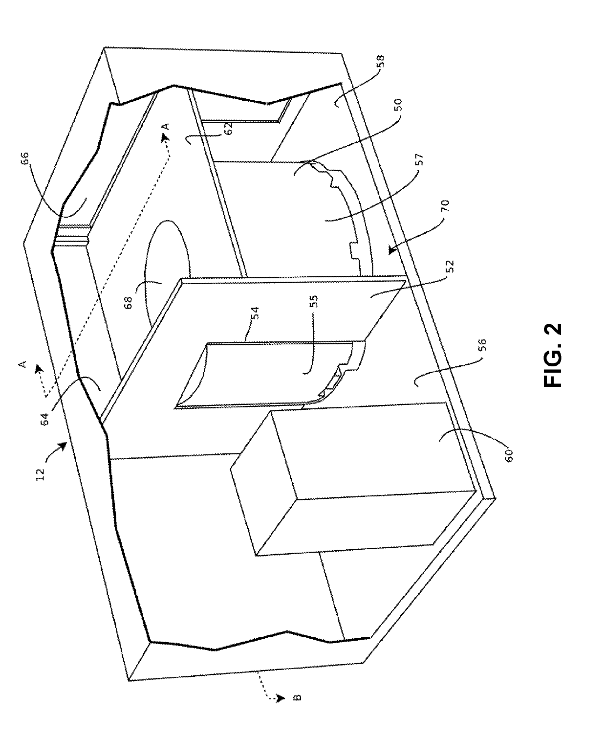
8. The apparatus of any one of embodiments 3-7, wherein: the building comprises a second room separated from the f...


PUM


Abstract

Provided is a rack, comprising: a plurality of rack units; and a plurality of lockers each housing a different respective subset of the rack units, wherein respective lockers among the plurality comprise: a first respective barrier disposed between a respective pair of the rack units; a second respective barrier disposed between another respective pair of the rack units; a third respective barrier that is orthogonal to the first barrier and the second barrier, the third respective barrier being moveably or removeably coupled to the rack; a respective volume configured to receive one or more computing devices; and a respective lock configured to secure the third respective barrier to the rack in the closed position when in a locked state.

Description

CROSS-REFERENCE TO RELATED APPLICATIONS[0001]The present patent filing claims the benefit of, and thus is a non-provisional of, U.S. Provisional Patent Application 62 / 594,221, filed 4 Dec. 2017, titled MODULAR DATA CENTER. The entire content of each afore-mentioned patent filing is hereby incorporated by reference.BACKGROUND1. Field[0002]The present disclosure relates generally to data centers and, more specifically, to selective-access data center racks in modular data centers and other data centers.2. Description of the Related Art[0003]In recent years, industry and consumers have come to increasingly rely upon data centers for computing services. These facilities generally aggregate relatively large amounts of computing power and include relatively complex infrastructure providing network connections, power distribution, and thermal management for the computing devices within the facility. A trend in recent years has been towards ever greater consolidation of computing power in f...

Claims


Application Information

Patent Timeline
IPC IPC(8): G06F21/31H05K7/18H05K7/14H05K7/20E04H5/02
CPCG06F21/31H05K7/183H05K7/1495H05K7/2079H05K7/1497H05K7/20745H05K7/20836H05K7/1498E04H5/02H02S20/22E05B47/0002G06F21/86E04H2005/005Y02E10/50Y04S40/20Y02B10/10H05K7/20209A62C37/40G05B19/042G05B2219/2614G05B2219/2639H05K7/18
Inventor CRAWFORD, COLTON MALONEWHITE, STEVENCHAVEZ, BENBASSO, FRANK
Owner VAPOR IO INC
Why Eureka
Try Eureka