Pneumatic Tire

a technology of pneumatic tires and tires, applied in the field of pneumatic tires, can solve the problems of uneven wear resistance, easy to slip, and easy to slip, and achieve the effect of improving uneven wear resistance and driving performance, and good balan

Inactive Publication Date: 2019-06-13
THE YOKOHAMA RUBBER CO LTD
View PDF0 Cites 6 Cited by
  • Summary
  • Abstract
  • Description
  • Claims
  • Application Information

AI Technical Summary

Benefits of technology

[0004]The present technology provides a pneumatic tire capable of improving uneven wear resistance and driving performance on muddy road surfaces, and of achieving a good balance of both of these performance properties in a compatible manner.

Problems solved by technology

However, uneven wear tends to easily occur with this type of tread pattern configured with primarily of blocks.
In particular, when the groove surface area is increased to improve mud performance, block rigidity decreases, resulting in a decrease of uneven wear resistance, and thus a problem is that it is difficult to achieve both mud performance and uneven wear resistance in a compatible manner.

Method used


Image

  • Pneumatic Tire
  • Pneumatic Tire
  • Pneumatic Tire

Examples


examples

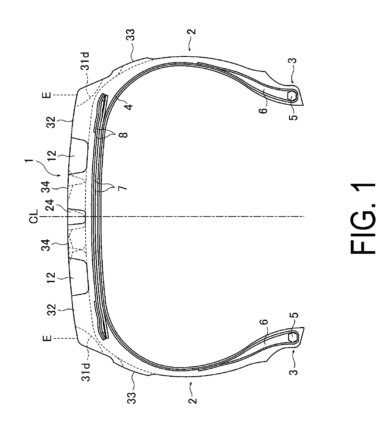
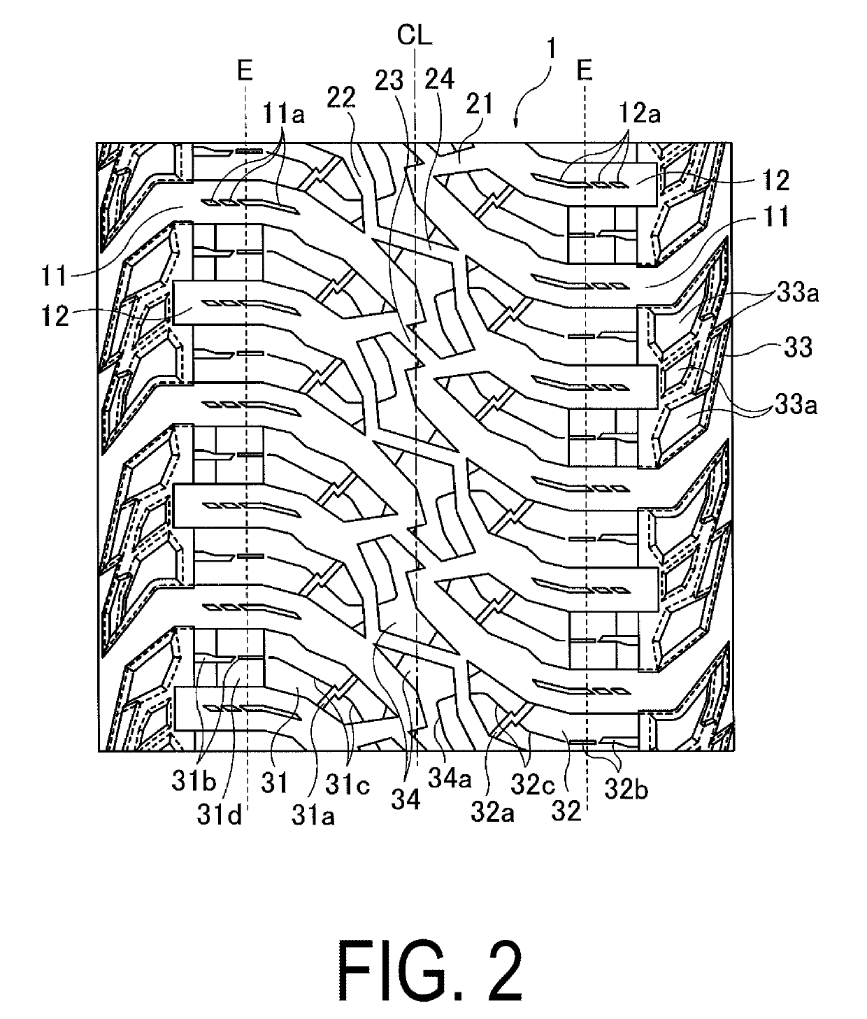
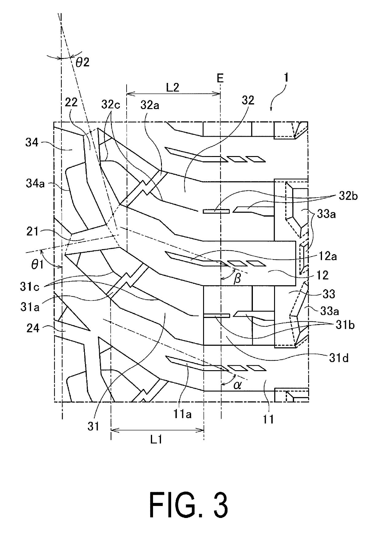
[0049]Nine types of pneumatic tires were prepared and used respectively as a Conventional Example 1 and Examples 1 to 8. For each tire, the tire size was LT265 / 70R17, the basic structure illustrated in FIG. 1 was used, the tread patterns were based on the tread pattern of FIG. 2, and the magnitude relationship of the angles of the first connection groove and the second connection groove (first / second connection groove angles), the angle α with respect to the tire circumferential direction at the traversal groove position and a ground contact edge position of the first lug groove, the angle β with respect to the tire circumferential direction at the ground contact edge position of the second lug groove, the presence or lack of third connection grooves and fourth connection grooves (presence of third / fourth connection grooves), the magnitude relationship of the angle θ3 of the third connection groove with respect to the tire circumferential direction and the angle θ4 of the fourth con...


PUM


Abstract

A pneumatic tire includes first lug grooves and second lug grooves shorter than the first lug grooves provided alternately along a circumferential direction in a shoulder region of a tread section, a first connection groove that connects the second lug groove and a tip end part of the first lug groove, and a second connection groove that connects the first lug groove and a tip end part of the second lug groove. An angle of the first connection groove is greater than an angle of the second connection groove, and an inner end portion in the lateral direction of each of first shoulder blocks, each defined by the first lug groove, the second lug groove, and the first connection groove, is disposed closer to the equator side than an inner end portion in the lateral direction of each of second shoulder blocks.

Description

TECHNICAL FIELD[0001]The present technology relates to a pneumatic tire, and more specifically, relates to a pneumatic tire capable of improving uneven wear resistance and driving performance on muddy road surfaces, and achieving a good balance of both of these performance properties in a compatible manner.BACKGROUND ART[0002]With pneumatic tires that are used for driving on muddy ground, snow covered roads, and sandy soil, etc. (hereinafter, collectively referred to by the generic phrase “muddy ground, etc.”), ordinarily, tires having a large groove surface area with a tread pattern configured with primarily of blocks and lug grooves having a large amount of edge components are adopted. This type of tire is configured to obtain traction performance by biting into mud, snow, and sand, etc. (hereinafter, collectively referred to by the generic phrase “mud, etc.”) on road surfaces, to prevent the mud, etc. from being packed into the grooves (increase discharge performance of mud, etc....

Claims


Application Information

Patent Timeline
Patent Type & Authority Applications(United States)
IPC IPC(8): B60C11/03B60C11/01B60C11/12B60C11/13
CPCB60C11/0311B60C11/01B60C11/1204B60C11/1236B60C11/1353B60C2200/14B60C11/03B60C11/12B60C2011/0346B60C11/11B60C2011/1213B60C2011/0372B60C11/0306B60C2011/1209B60C2011/0344B60C2011/0365B60C2011/0381B60C11/1369B60C2011/1361
Inventor MURATA, TAKAHISA
Owner THE YOKOHAMA RUBBER CO LTD
Why Eureka
Try Eureka