
Arm-Supporting Structure

Active Publication Date: 2019-06-13
KUNSHAN HONGJIE ELECTRONICS CO LTD
View PDF28 Cites 5 Cited by
  • Summary
  • Abstract
  • Description
  • Claims
  • Application Information

AI Technical Summary

Benefits of technology

The present invention provides a bracket that can stably support electronic devices of any weight. The bracket has a self-balancing system that automatically adjusts its position, allowing for a balance of force to be achieved spontaneously. This protects the adjusting means from bearing a torque and makes the adjusting means easy to adjust. Additionally, the bracket is stable even when no electronic device is mounted on it, preventing it from tilting upward. This increases the weight range of electronic devices that can be suspended on the bracket. Overall, the bracket provides a stable and easy-to-adjust solution for supporting electronic devices of any weight.

Problems solved by technology

As a result, such an arm-structure has a limited bearing capacity which is normally from 3 kg to 9 kg.
When no or only a light electronic device is suspended, it is difficult to perform adjustment and the arm intends to lift up automatically.
Such an arm structure has a poor bearing capacity and is prone to being jammed.
This in turn requires great effort to make adjustment, and the adjustment may not be smooth.

Method used


Image

  • Arm-Supporting Structure
  • Arm-Supporting Structure
  • Arm-Supporting Structure

Examples


Embodiment Construction

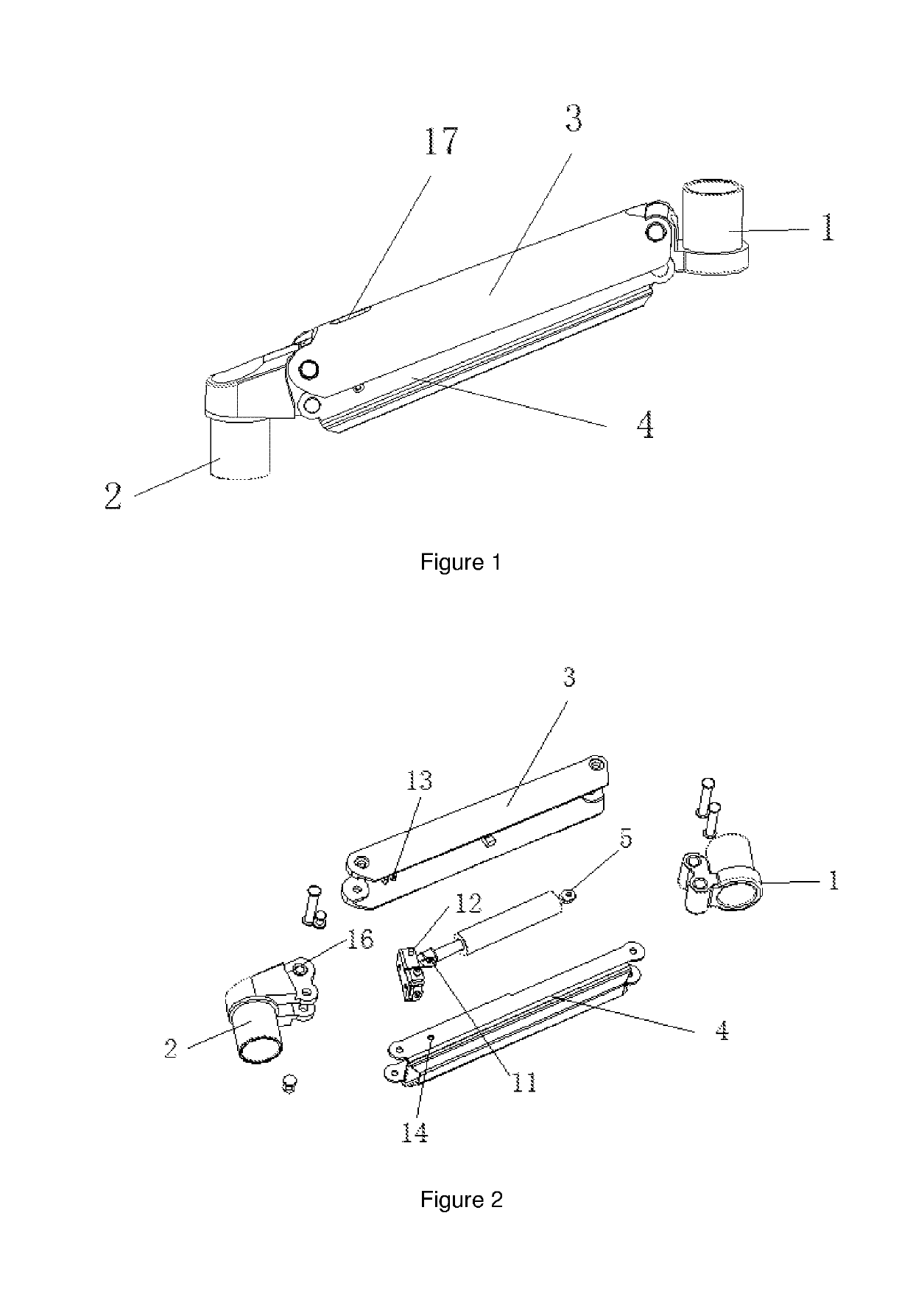
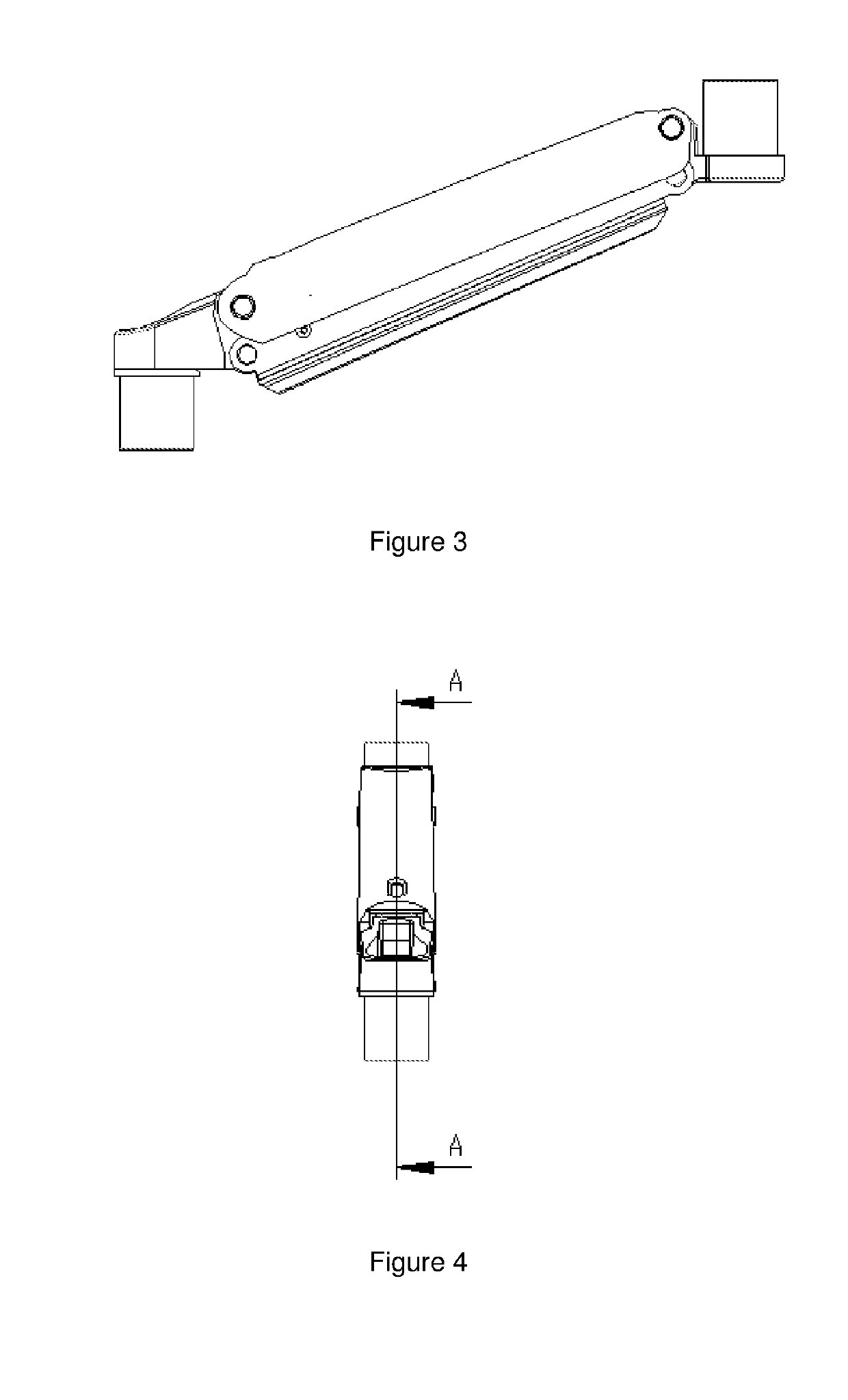
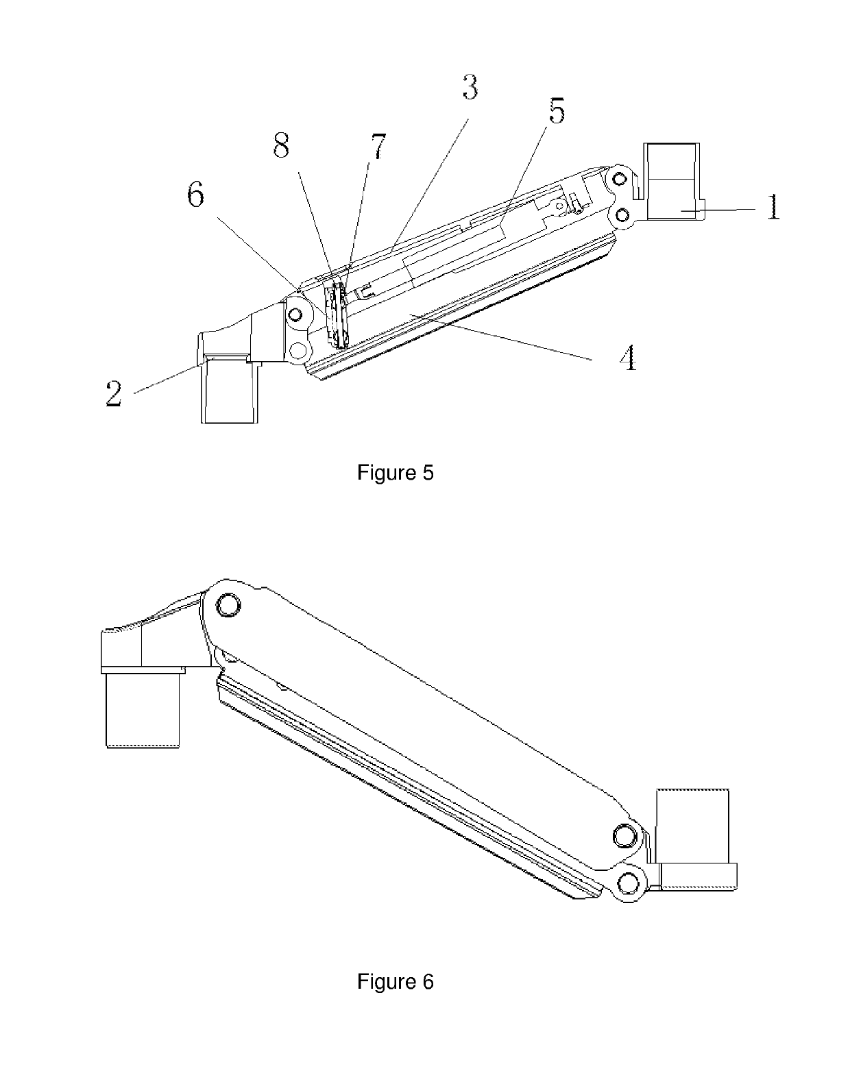
[0025]Example: an arm-supporting structure, including a front arm connector 1, a rear arm connector 2, an adjusting means for an upper support 3 and a lower support 4, and an elastic supporting means 5. The front arm connector 1, the upper support 3, the rear arm connector 2 and the lower support 4 are hingedly connected sequentially to form a parallelogram structure. The upper end and the lower end of the adjusting means are hingedly connected with the upper support 3 and the lower support 4, respectively. Two ends of the elastic supporting means 5 are connected to the adjusting means and the upper support 3, respectively, and the length of the elastic supporting means 5 is elastically stretchable.

[0026]During the use, the front arm connector 1, the upper support 3, the rear arm connector 2 and the lower support 4 form a parallelogram structure (the parallelogram structure ensures that the front and rear connectors have the same motion angle. The rear arm connector 2 forms an overa...


PUM


Abstract

Provided is an arm-supporting structure, including a front arm connector, a rear arm connector, an adjusting means for an upper support and a lower support, and an elastic supporting means. The front arm connector, the upper support, the rear arm connector and the lower support are articulated sequentially to form a parallelogram structure. The upper end and the lower end of the adjusting means are articulated with the upper support and the lower support, respectively. Two ends of the elastic supporting means are connected with the adjusting means and the upper support, respectively. The elastic supporting means has a length that is elastically stretchable. The adjusting means automatically adjusts its position in accordance with the swinging of the upper support and the lower support, shifts the position of the fulcrum of the elastic supporting means, and automatically reaches a balance of force.

Description

CROSS-REFERENCE TO RELATED APPLICATIONS[0001]The present application claims a priority of Chinese Patent Application No. 201711286937.X filed with the China Patent Office on Dec. 7, 2017, the content of which is incorporated herein to its entirety.TECHNICAL FIELD[0002]The present disclosure relates to a bracket, and particularly to an arm-supporting structure.BACKGROUND ART[0003]In general, brackets for mounting electronic devices, such as display bracket, television bracket and projector bracket, are made to support an electronic device and adjust its height through an arm. At present, the arm-structure for height adjustment and support is achieved as follows. One end of both of the upper support and the lower support is articulated (i.e., in hinge connection) to a base, and the other end thereof is articulated to a connector. The base is provided thereon with a screw which is locked in axial direction but rotatable in a circumferential direction. A nut screw that is connected onto...

Claims


Application Information

Patent Timeline
IPC IPC(8): F16M13/02F16F9/02
CPCF16M13/022F16F9/0245F16M2200/063F16F2230/0005F16M11/00F16M11/04F16M11/121F16F9/54F16M11/046F16M11/048F16M2200/041
Inventor CHANG, XIAOJIE
Owner KUNSHAN HONGJIE ELECTRONICS CO LTD
Learn More