Method and kit for modifying a corrugated sign assembly

a technology of corrugated signs and kits, which is applied in the direction of signs, instruments, machine supports, etc., can solve the problems of limiting the size of the support, reducing the stability of reducing the stability of the overall sign, so as to increase the stability of the corrugated display apparatus, increase the overall sign stability, and increase the weight

Active Publication Date: 2015-03-24
CEPEK WILLIAM BARRY
View PDF52 Cites 4 Cited by
  • Summary
  • Abstract
  • Description
  • Claims
  • Application Information

AI Technical Summary

Benefits of technology

[0006]With the foregoing and other objects in view, there is provided, in accordance with the invention, a method of increasing the stability of a corrugated display apparatus that defines a plurality of lower openings and having a plurality of walls at least partially defining a plurality of channels, each of the plurality of channels having a channel width. The plurality of channels span from one of the plurality of lower openings toward an upper end of the display apparatus. The method includes providing a cutting device having a first end, a second end, a handle length separating the first and second ends, and a blade member coupled along the handle length. The method also includes cutting a portion of at least one of the plurality of walls with the blade member to combine at least two of the plurality of channels adjacent to the cut portion of the at least one of the plurality of walls to create an enlarged channel, and then inserting a post-like member into the enlarged channel, the post-like member securely retained within the enlarged channel. This process creates a display apparatus that is operable to not only support signs of a greater weight but also increases the overall sign stability when placed in environments with inclement weather.

Problems solved by technology

The problem with supporting the sign with a rod through a single corrugation channel is that the channel is limited in size, thereby limiting the size of the support.
As a result, the support arm(s) are weak and susceptible to damage when exposed to environments having harsh weather conditions, e.g., wind, snow, and rain.
To that end, strong winds cause the support arms to either buckle under the weight or become dislodged from their placement location.
The problem is exacerbated as the surface area of the sign increases because the air resistance increases.
To overcome this problem, the prior corrugated signs have included a channel affixed to the outer surface of the corrugated sign, i.e., one face of the sign, which is unattractive and ruins the smooth professional appearance.
Those known corrugated signs also have channels that are difficult to modify because the openings are very small, have walls of a material that is difficult to cut, and there is limited availability of tools capable of adjusting the channel widths to accommodate any larger sized support arm(s).
Additionally, attaching the sign to a rod or other securement member on the face of the sign covers or significantly distorts the advertising of the sign face.

Method used


Image

  • Method and kit for modifying a corrugated sign assembly
  • Method and kit for modifying a corrugated sign assembly
  • Method and kit for modifying a corrugated sign assembly

Examples


Embodiment Construction

[0044]While the specification concludes with claims defining the features of the invention that are regarded as novel, it is believed that the invention will be better understood from a consideration of the following description in conjunction with the drawing figures, in which like reference numerals are carried forward. It is to be understood that the disclosed embodiments are merely exemplary of the invention, which can be embodied in various forms.

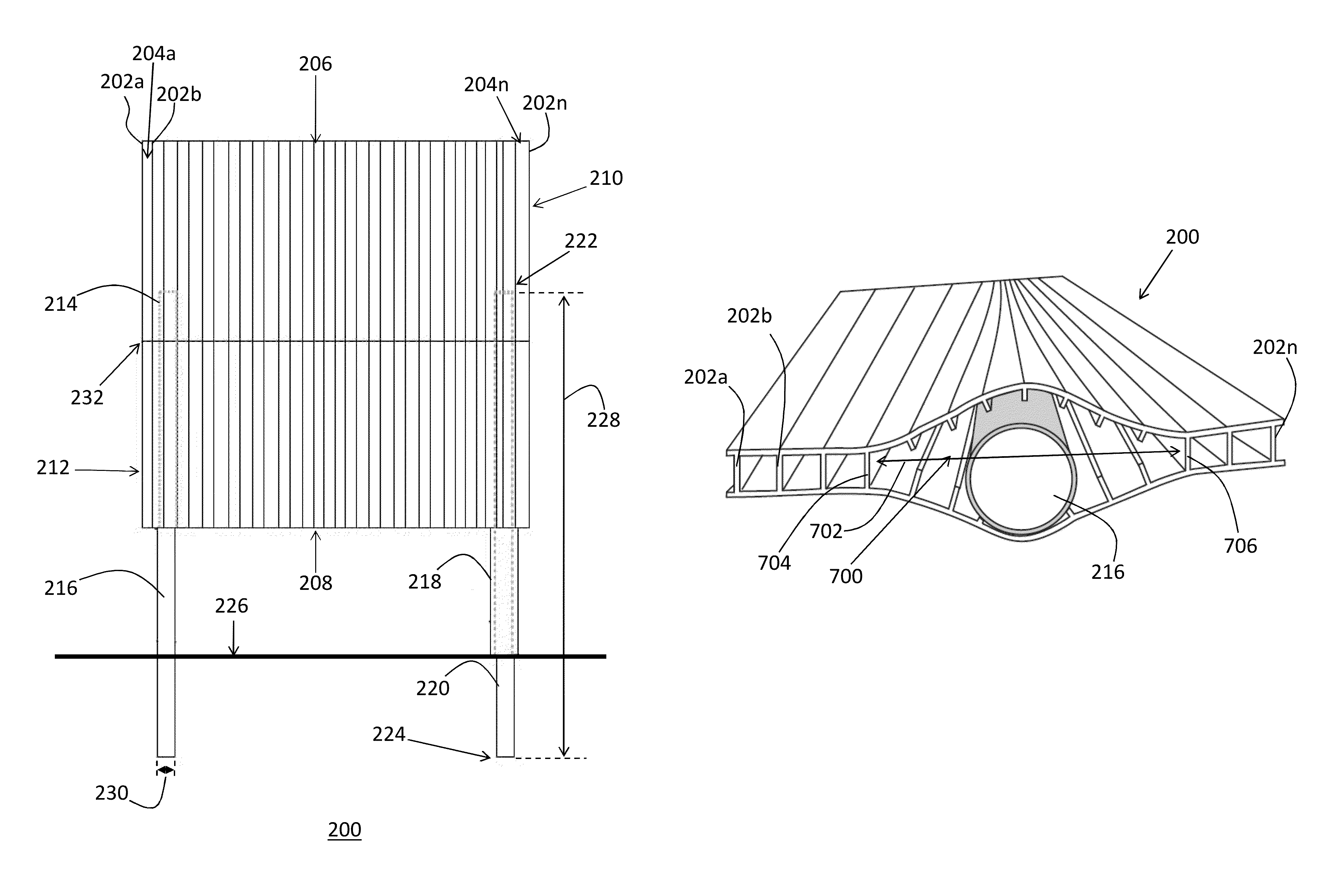
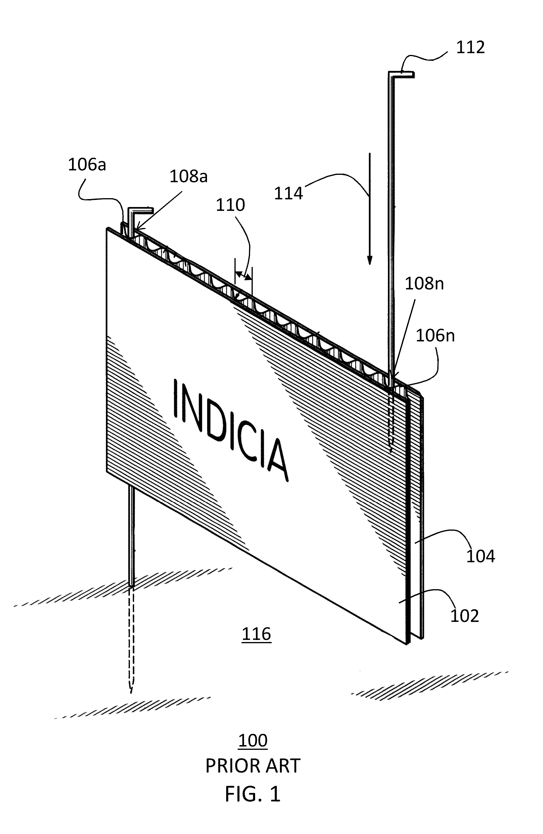
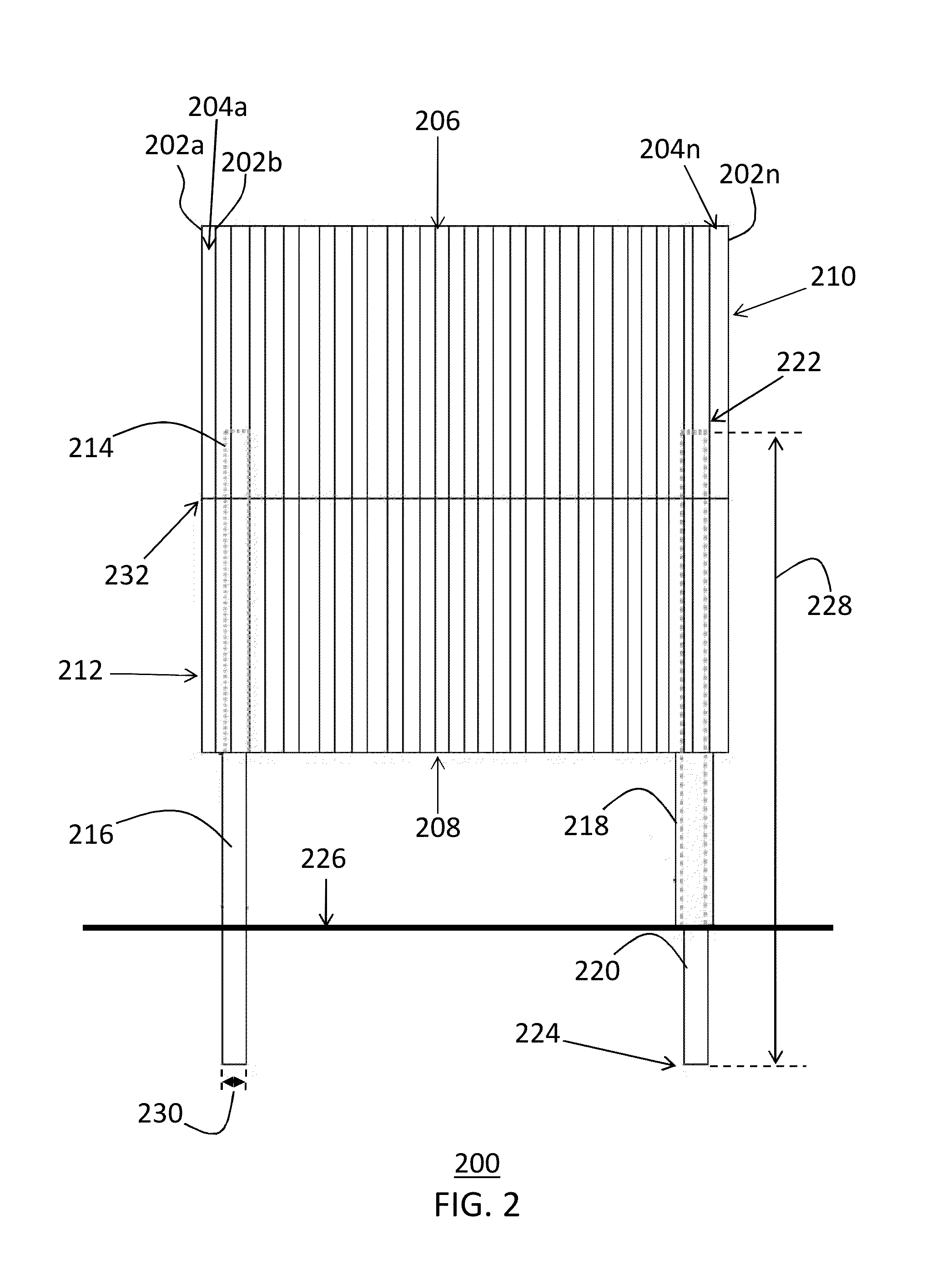
[0045]The present invention provides a novel and efficient method of modifying those standard corrugated signs by cutting the walls with a special cutting device, thereby combining the channels of the corrugated structure. As shown in FIG. 1, standard corrugated signs 100 include an outer face 102 that includes some indicia of advertising, message(s), or other content displayed for the viewing public and an inner face 104. The sign 100 has a plurality of walls 106a-n separating the outer and inner faces 102, 104, wherein “a” represents...


PUM

PropertyMeasurementUnit
widthaaaaaaaaaa
forceaaaaaaaaaa
stabilityaaaaaaaaaa

Abstract

A method of increasing the stability of a corrugated display apparatus defining a plurality of lower openings and having a plurality of walls at least partially defining a plurality of channels, each with a channel width, spanning from one of the plurality of lower openings toward an upper end of the display apparatus, the method including providing a cutting device with a handle length and a blade member coupled along the handle length, cutting a portion of at least one of the plurality of walls with the blade member to combine two of the plurality of channels adjacent to the cut portion of the at least one of the plurality of walls to create an enlarged channel, and inserting a post-like member into the enlarged channel, the post-like member securely retained within the enlarged channel.

Description

FIELD OF THE INVENTION[0001]The present invention relates generally to a method and kit for modifying a corrugated sign assembly to increase its stability, and more particularly relates to a method and kit for altering a configuration of a corrugated sign for attachment to a support arm.BACKGROUND OF THE INVENTION[0002]Corrugated signs, such as yard signs, are well known in the art and are used extensively in the advertising industry for displaying advertisements because of their low cost and smooth professional appearance. For example, the signs are commonly employed by real estate agents for advertising home sales and rentals by placing a corrugated sign on a frame post in the front yard of the house. For another example, corrugated signs are commonly placed in grassy medians to advise drivers in opposite directions of temporary traffic flows and special events.[0003]These signs are commonly held upright by way of two arms whereby each arm slides into a single channel of the corru...

Claims


Application Information

Patent Timeline
Patent Type & Authority Patents(United States)
IPC IPC(8): G09F15/00G09F7/18
CPCG09F7/18G09F2007/1826B26B3/08G09F7/22G09F2007/1804G09F2007/1834Y10T29/49826
Inventor CEPEK, WILLIAM BARRY
Owner CEPEK WILLIAM BARRY
Why Eureka
Try Eureka