Backing component in ultrasound probe

a technology of backing component and ultrasound probe, which is applied in the direction of mechanical vibration separation, additive manufacturing processes, instruments, etc., can solve problems such as poor image quality

Active Publication Date: 2019-06-13
GENERAL ELECTRIC CO
View PDF0 Cites 4 Cited by
  • Summary
  • Abstract
  • Description
  • Claims
  • Application Information

AI Technical Summary

Problems solved by technology

Conventional techniques for forming multiple attenuation zones in a backing component, often result in boundary layer effect resulting in poor image quality.

Method used


Image

  • Backing component in ultrasound probe
  • Backing component in ultrasound probe
  • Backing component in ultrasound probe

Examples


Embodiment Construction

[0012]As used herein, an element or step recited in the singular and proceeded with the word “a” or “an” should be understood as not excluding plural elements or steps, unless such exclusion is explicitly recited. As used herein, the term “or” is not meant to be exclusive and refers to at least one of the referenced components being present and includes instances in which a combination of the referenced components may be present, unless the context clearly dictates otherwise.

[0013]Approximating language, as used herein throughout the specification and claims, may be applied to modify any quantitative representation that could permissibly vary without resulting in a change in the basic function to which it is related. Accordingly, a value modified by a term or terms, such as “about”, and “substantially” is not to be limited to the precise value specified. In some instances, the approximating language may correspond to the precision of an instrument for measuring the value. Here and t...


PUM

PropertyMeasurementUnit
median particle sizeaaaaaaaaaa

Abstract

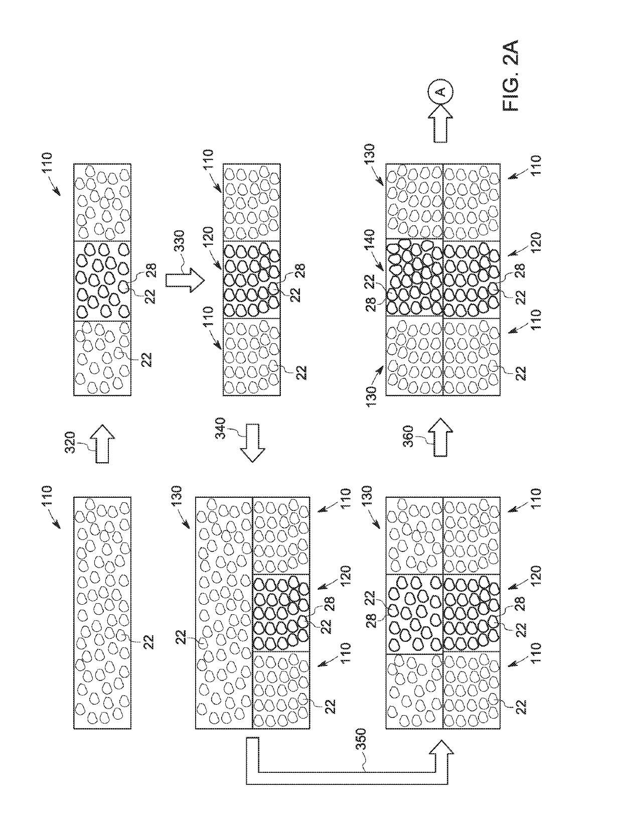
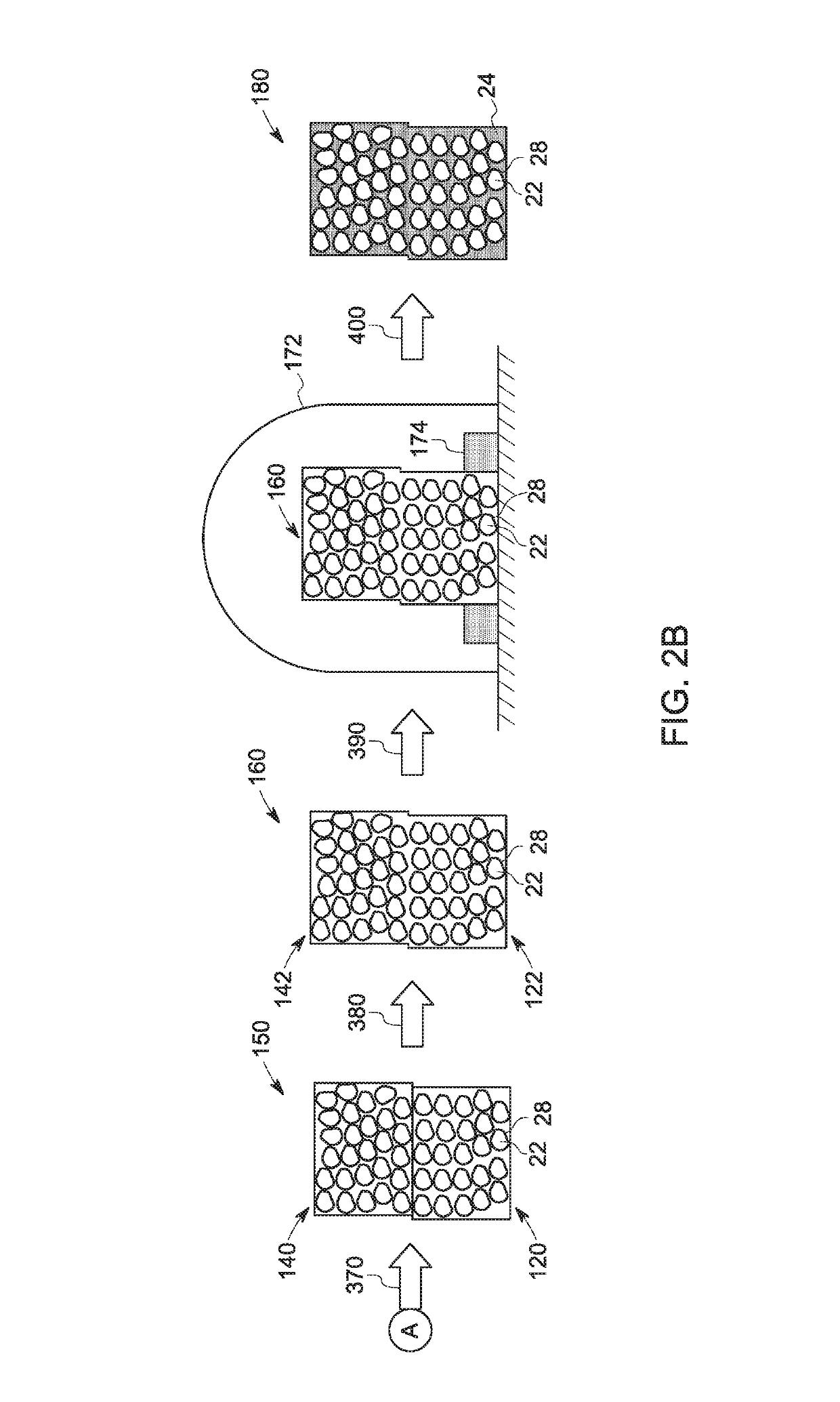
A backing component configured to receive and attenuate transmitted acoustic signals from a transducer element in an ultrasound probe is disclosed. The backing component has a unitary structure of a first material and a second material, and a variation in packing density of the first material across at least a portion of a thickness of the backing component. Further, a method of making a backing component for a transducer element in an ultrasound probe is disclosed. The method includes performing an additive manufacturing technique using a first material and a second material to form the backing component that has a unitary structure of the first material and the second material. Performing the additive manufacturing technique involves varying a packing density of the first material across at least a portion of thickness of the backing component.

Description

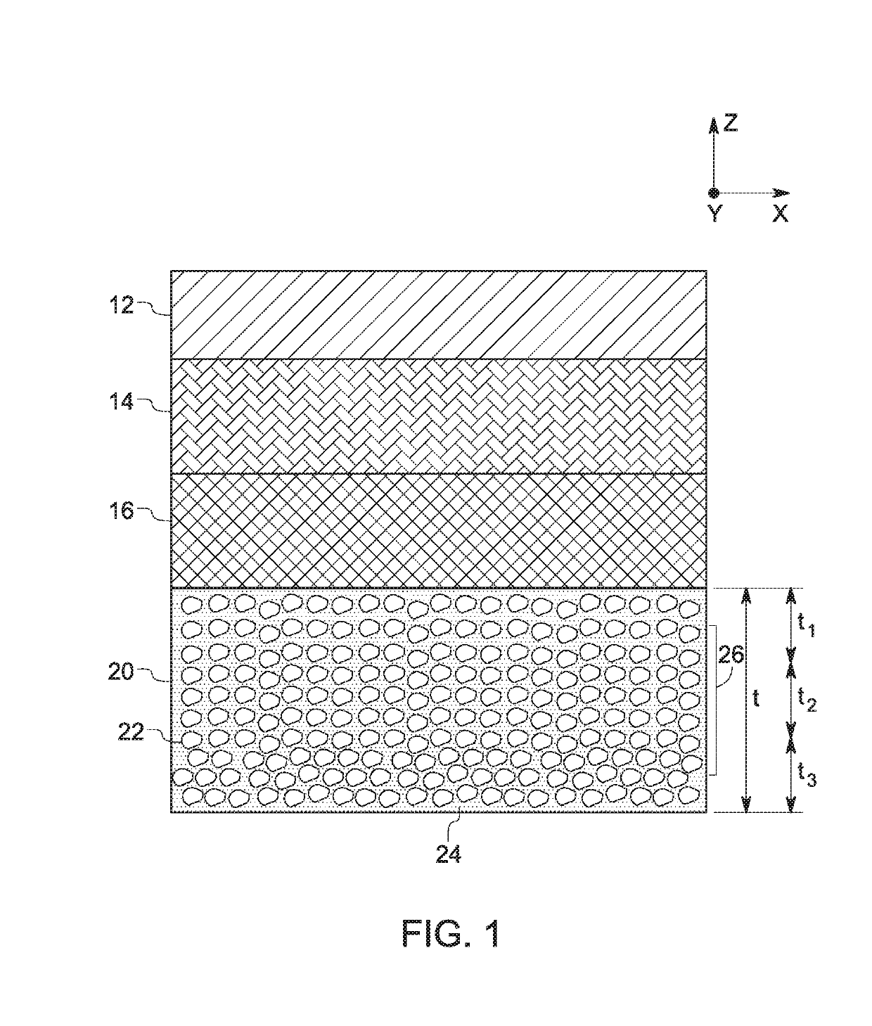
BACKGROUND[0001]Embodiments of the disclosure generally relate to a backing component for a transducer element in an ultrasound probe. More particularly, embodiments of the disclosure relate to a backing component having a unitary structure and method for manufacturing the backing component using additive manufacturing techniques.[0002]There are various technical requirements of a backing component for an ultrasonic transducer element of an ultrasound probe. According to one requirement, it may be desirable to prevent or minimize the reflection of acoustic signals by the backing component or a back surface of the backing component. Further, it may be desirable that the backing component participates in damping the undesired sound reverberation created by the ultrasonic transducer element to control the pulse duration of the ultrasonic signal outgoing from the ultrasonic transducer element for imaging process.[0003]Therefore, it may be desirable to have a backing component that has a...

Claims


Application Information

Patent Timeline
Patent Type & Authority Applications(United States)
IPC IPC(8): G01N29/24B29C64/165B33Y10/00B33Y80/00G01N29/22G01D11/10
CPCG01N29/24B29C64/165B33Y10/00B33Y80/00G01N29/221G01D11/10B29K2063/00B29K2103/06B29K2995/0002A61B8/4483G10K11/002B06B1/0685G10K11/165
Inventor ABRAHAM, JESSICA LYNNBEACHAM, JIMMIE AUTREYEASTERBROOK, SCOTT WILLIAM
Owner GENERAL ELECTRIC CO
Why Eureka
Try Eureka