
Fixation clamp with spacer

Active Publication Date: 2019-06-20
AUSTIN MILLER TRAUMA LLC
View PDF0 Cites 3 Cited by
  • Summary
  • Abstract
  • Description
  • Claims
  • Application Information

AI Technical Summary

Benefits of technology

These systems have the ability to clamp different sized elements with one jaw set, which reduces the need for multiple clamps. They also provide higher clamping loads on the fixation elements for the same fastener load. The systems have a jaw set that can be rotated relative to a reference component, which makes it easier to clamp the fixation elements. The technical effect is improved stability and efficiency in external fixation clamps.

Problems solved by technology

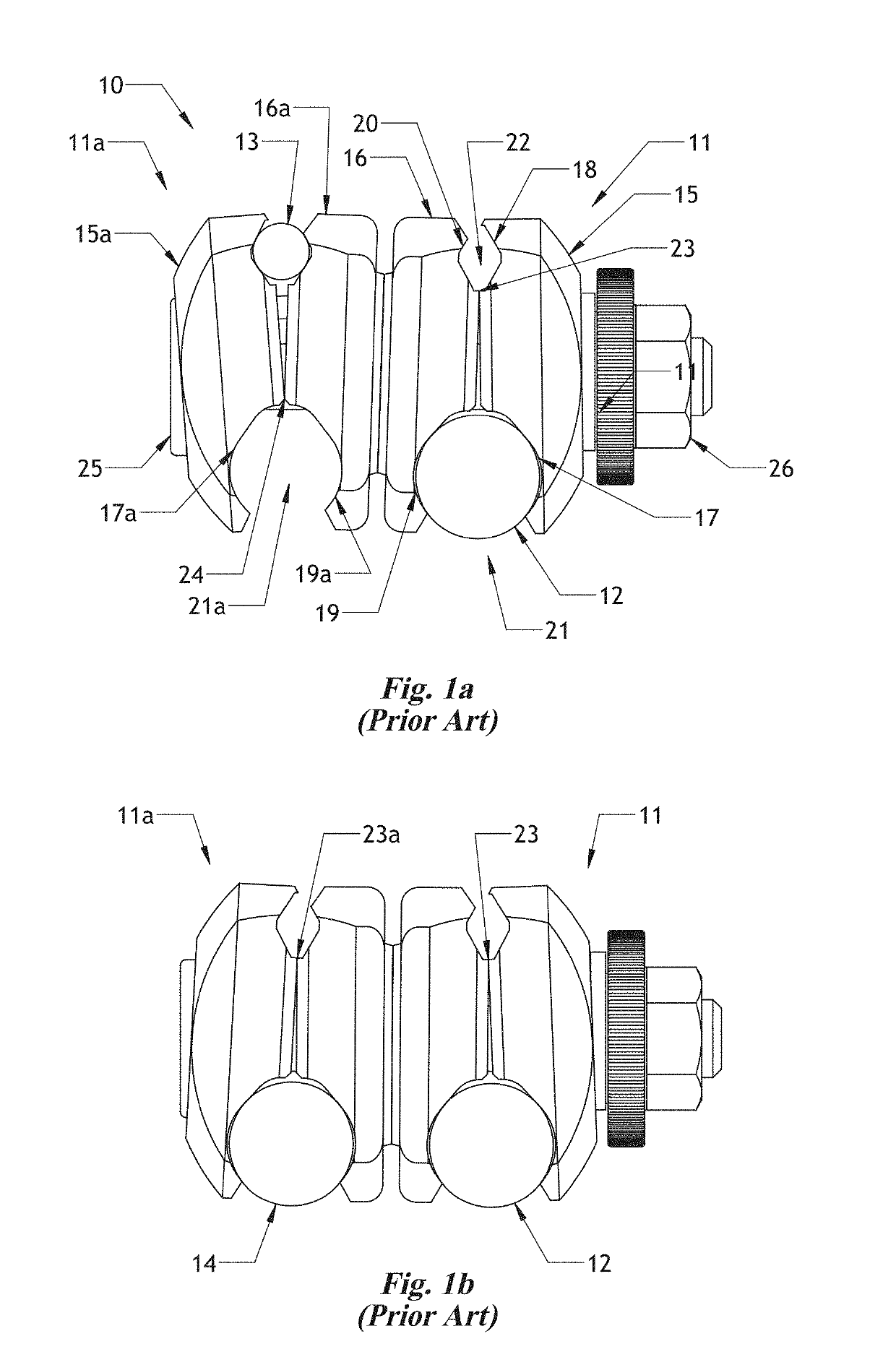
Although a jaw set can be configured to grab a range of sizes of elements, fitting elements that have an over two times difference in diameter in a jaw set that is both compact in size and effective in locking strength has been a challenge.
Having separate clamps for joining two bars versus joining a bar to a pin can lead to problems.
The user can accidentally get handed the wrong one during a medical procedure, leading to wasted time.
The shaft tightening element can be in an inconvenient location for the desired frame geometry.
One example drawback is that the amount of force transferred to the element by the jaw geometry is reduced relative to a standard one sided clamp.
One drawback of this design is the spacer can move to the wrong position such that the jaw set is configured for a different element size than intended.
Another drawback is that it is difficult to configure the jaw passage and the steps such that elements of as much as two times difference in size can be effectively gripped.

Method used


Image

  • Fixation clamp with spacer
  • Fixation clamp with spacer
  • Fixation clamp with spacer

Examples


Embodiment Construction

[0061]For the purposes of promoting an understanding of the principles of the present disclosure, reference will now be made to the embodiments illustrated in the drawings, and specific language will be used to describe the same. It will nevertheless be understood that no limitation of the scope of the disclosure is intended. Any alterations and further modifications to the described devices, instruments, methods, and any further application of the principles of the present disclosure are fully contemplated as would normally occur to one skilled in the art to which the disclosure relates. In particular, it is fully contemplated that the features, components, and / or steps described with respect to one embodiment may be combined with the features, components, and / or steps described with respect to other embodiments of the present disclosure.

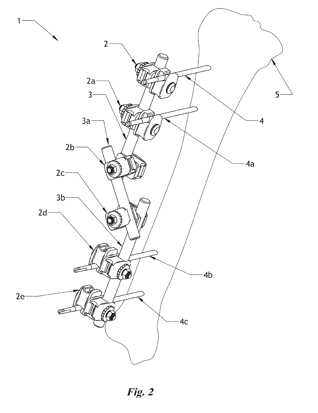
[0062]FIG. 2 shows one type of external fixation frame 1. The frame may be held together with a number of clamps 2, 2a, 2b, 2c, 2d, 2e. Each clamp...


PUM


Abstract

A clamping device of an external fixation system that has a jaw set with a passage at one end configured to hold an element from a first range of sizes and a second passage configured to hold an element from a different range of sizes. The jaw set includes a first jaw, a second jaw, and a slider interposed between the first and second jaws that moves to a first position when the first element is located in the first passage and to a second position when the second element is located in the second passage.

Description

PRIORITY[0001]The present disclosure claims priority to and the benefit of the filing date of U.S. Provisional Patent Application 62 / 689,437, filed Jun. 25, 2018 and U.S. Provisional Patent Application, 62 / 595,344, filed Dec. 6, 2017, both of which are incorporated by reference herein in their entireties.BACKGROUND[0002]External fixation systems are used to build frames that hold bone fixation elements, such as pins, bars, or rods, rigidly. The variability of the different conditions treated, such as bone fractures, requires versatility of alignment and sizing of the fixator frame. A very common style of external fixation system uses fixation elements, i.e. bars and bone pins, and clamps that hold the fixation elements together. Commonly, both pins and bars have circular cross sections, but typically, the bars are a larger diameter than the pins. For large frames for the leg and arm, the most common size bar is 11 mm, but they may vary between 8 and 13 mm, and the most common size p...

Claims


Application Information

Patent Timeline
IPC IPC(8): A61B17/64
CPCA61B17/645A61B17/6416A61B2560/0406A61B2560/0443A61B17/66A61B17/6458A61B17/6466
Inventor MILLER, STEPHEN T.
Owner AUSTIN MILLER TRAUMA LLC
Learn More