Three-stage variable color paste pump and operation method thereof

Active Publication Date: 2019-06-27
ZHENGZHOU SANHUA TECH & IND
View PDF0 Cites 0 Cited by
  • Summary
  • Abstract
  • Description
  • Claims
  • Application Information

AI Technical Summary

Benefits of technology

The present invention allows for three-stage ejection, or a large, medium, and small amount of ejection, using one differential pump. This ensures precise ejection of color paste, particularly in small stages, and is easy to use, space-efficient, and convenient. The color mixer made by this pump is easy to operate and takes up minimal floor space.

Problems solved by technology

However, an existing reciprocating pump for ejecting a large amount of color paste may cause a relatively large ejection deviation when ejecting a small amount of color paste due to the large ejection amount in a unit travel, even if a small deviation occurs on the pump travel, thus causing color abnormality and failing to meet the product demands.
Although this can well solve the problem of controlling the amount of the pumped color paste, as the two color mixers are provided, a lot of money is spent, and a large space is also required, thereby being inconvenient to use, not meeting the needs of modern economic intensive production, and particularly unsuitable for use in storefronts; and another solution is to co-use a large pump with a large section cylinder and a small pump with a small section cylinder in parallel in the same pump and to arrange two pumping systems including one for ejection a large amount of color paste and the other for injecting a small amount of color paste, which also has the problems that the occupied space is relatively large, the structure is complex and the cost is high.

Method used


Image

  • Three-stage variable color paste pump and operation method thereof
  • Three-stage variable color paste pump and operation method thereof
  • Three-stage variable color paste pump and operation method thereof

Examples


Embodiment Construction

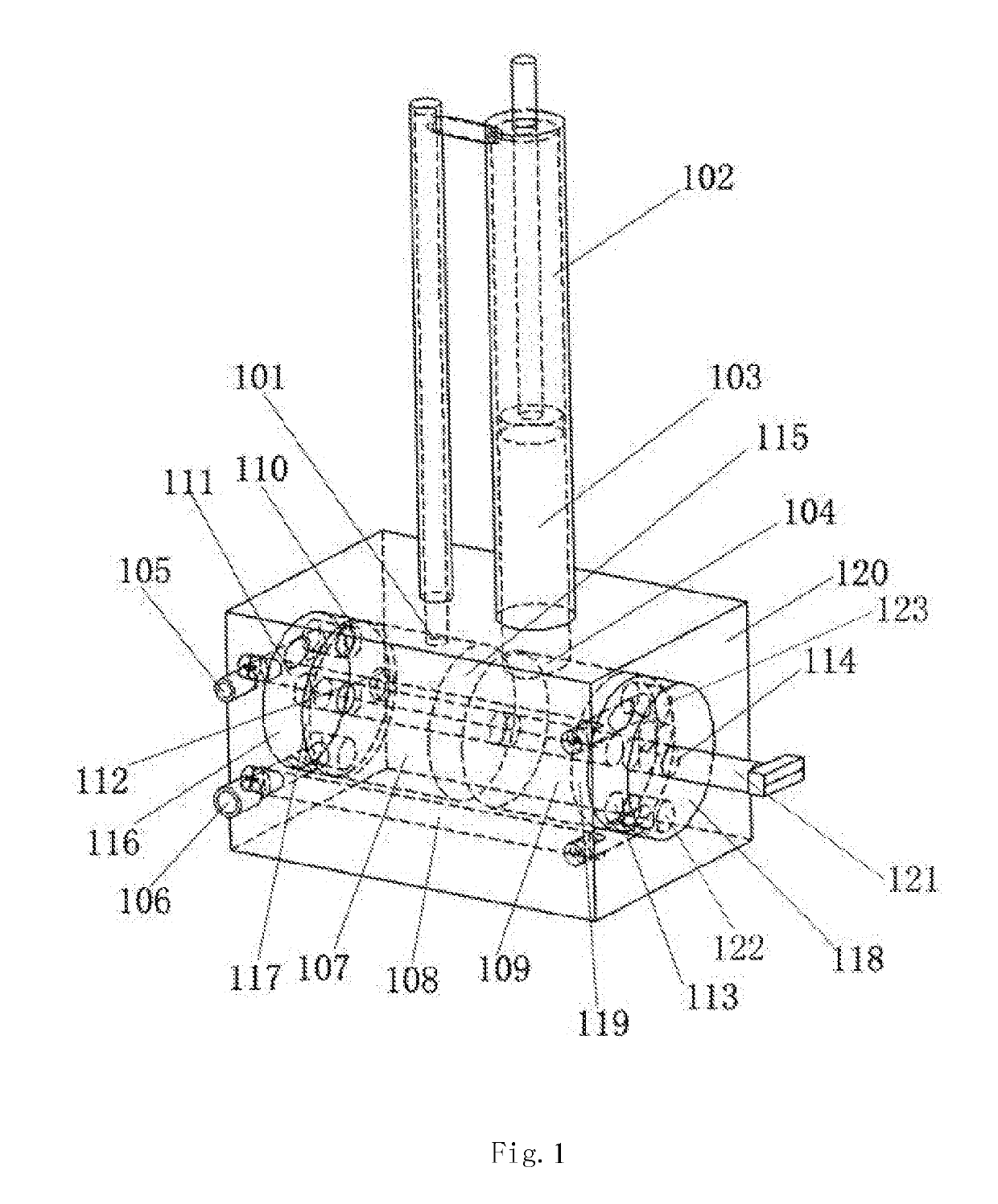
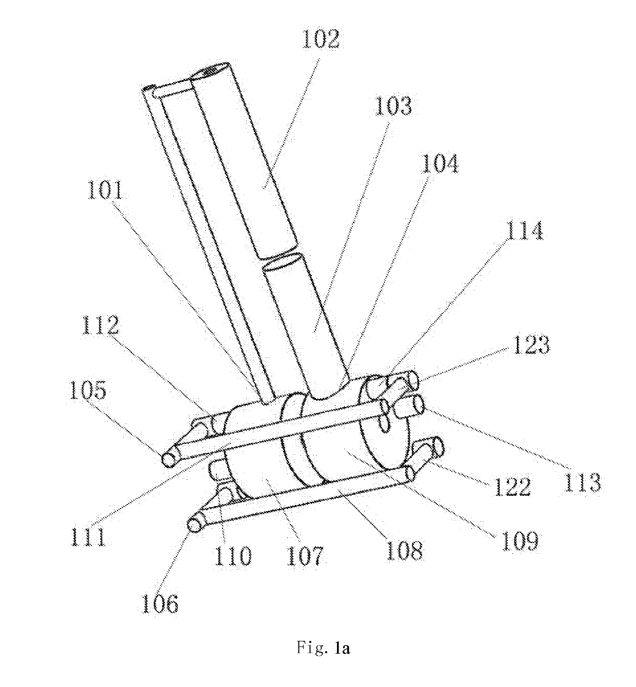
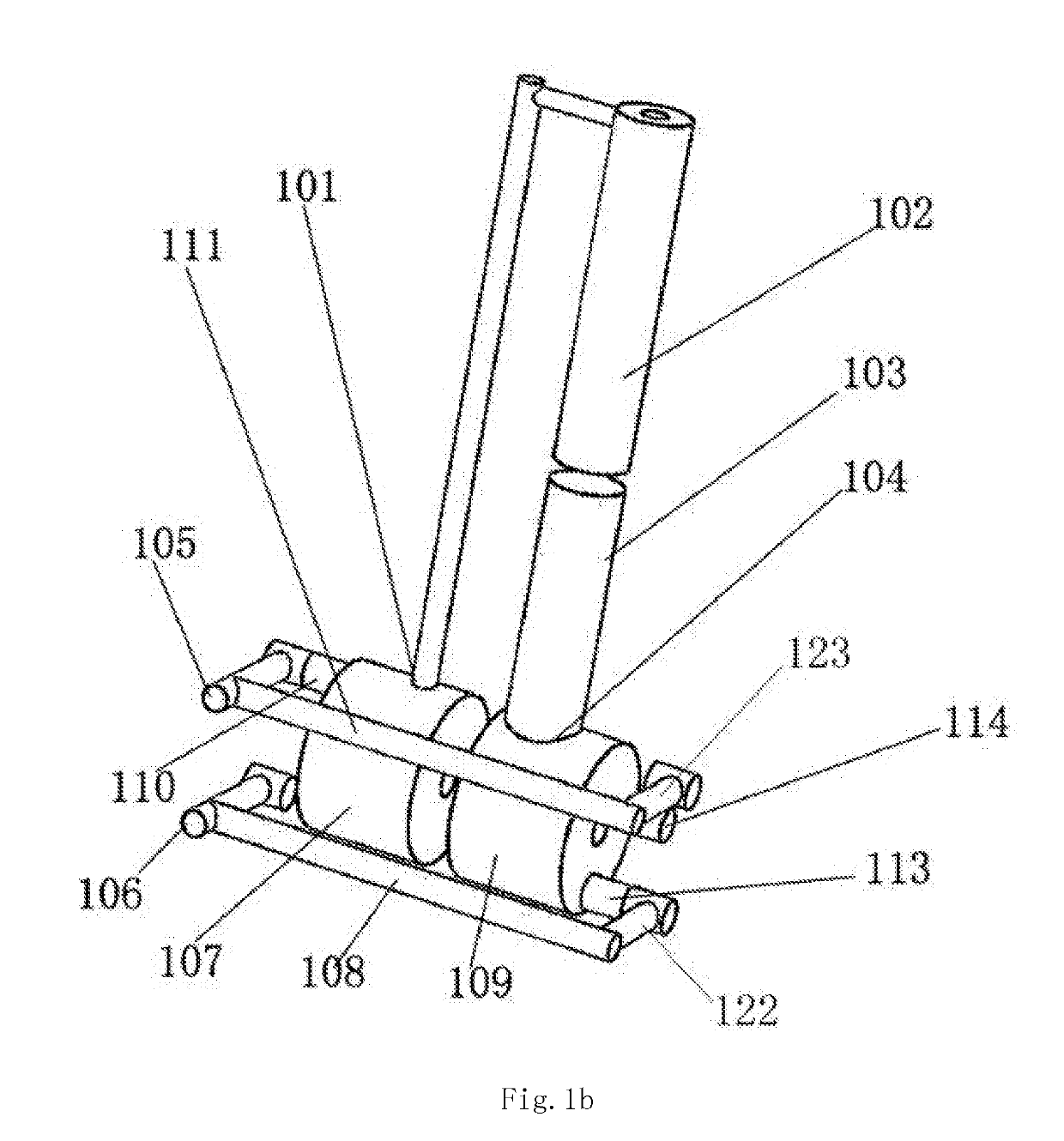
[0083]A three-stage variable color paste pump includes a differential pump, the differential pump includes a rodless cavity, a rod containing cavity and a piston rod, a control valve is provided, the control valve includes a valve body and a valve core, the valve body is provided with a rod containing cavity opening for communicating with the rod containing cavity, is provided with a rodless cavity opening for communicating with the rodless cavity, is provided with a color paste bucket opening for communicating with a color paste bucket, and is provided with an ejection opening, a channel is arranged on the valve core, and the valve core is moved to different positions to form the following communication structures: at a position 1, the rodless cavity communicates with the ejection opening, and the rodless cavity communicates with the rod containing cavity; at a position 2, the rod containing cavity opening communicates with the ejection opening, and the rodless cavity communicates ...


PUM


Abstract

A three-stage variable color paste pump, comprising: a differential pump, which includes: a rodless cavity, a rod containing cavity, and a piston rod; configuring a control valve, which comprises a valve body and a valve core, wherein the valve body is provided with a rod containing cavity opening which is in communication with the rod containing cavity; configuring a rodless cavity opening as in communication with the rodless cavity, configuring a color paste tank opening as in communication with a color paste tank, and configuring an injection outlet; configuring a channel on the valve core, moving the valve core to different positions may form three communication structures. The pump uses one differential pump to achieve three-stage injection output, thus ensuring the accuracy of the injection output of the color paste pump. The pump has a simple structure, takes up a small surface area, and is easy to use.

Description

FIELD OF THE INVENTION[0001]The present invention belongs to the field of toning equipment, and in particular to a three-stage variable color paste pump and an operation method thereof.BACKGROUND OF THE INVENTION[0002]Toning has strict requirements on the amount of color paste. It is required that the error of the ejection amount of color paste should not exceed a certain percentage when a pump ejects a large amount of color paste, and the error of the ejection amount of color paste should not exceed a certain percentage when a small amount of color paste is ejected as well. However, an existing reciprocating pump for ejecting a large amount of color paste may cause a relatively large ejection deviation when ejecting a small amount of color paste due to the large ejection amount in a unit travel, even if a small deviation occurs on the pump travel, thus causing color abnormality and failing to meet the product demands. Therefore, as to the color paste ejection precision control stan...

Claims


Application Information

Patent Timeline
IPC IPC(8): F04B13/02F04B53/10F04B37/10F04B23/06F04B49/22
CPCF04B13/02F04B53/10F04B37/10F04B23/06F04B49/22B01F15/0416B01F15/0247F04B13/00F04B15/00F04B49/225F04B15/02F04B49/03F04B7/0023F04B5/02F04B49/06B01F35/831B01F35/717613
Inventor HUANG, SONGXUE, WEIDAN
Owner ZHENGZHOU SANHUA TECH & IND
Why Eureka
Try Eureka