
Room space Cooling with Improved Thermal Storage

a technology for room space and thermal storage, applied in the field of room space cooling with improved thermal storage, can solve the problems of poor grid management, insufficient generation capacity, and large limitation, and achieve the effect of lowering electricity use and cos

Active Publication Date: 2019-06-27
TWYCE ENERGY LTD
View PDF9 Cites 4 Cited by
  • Summary
  • Abstract
  • Description
  • Claims
  • Application Information

AI Technical Summary

Benefits of technology

The invention is a new way to store heat that can also cool down a room, which saves money on electricity.

Problems solved by technology

Some of these fluctuations are a result of poor grid management, inadequate generation capacity to meet demand or intermittency of renewable power generation sources.
This is a big limitation when power is not available.

Method used


Image

  • Room space Cooling with Improved Thermal Storage
  • Room space Cooling with Improved Thermal Storage
  • Room space Cooling with Improved Thermal Storage

Examples


Embodiment Construction

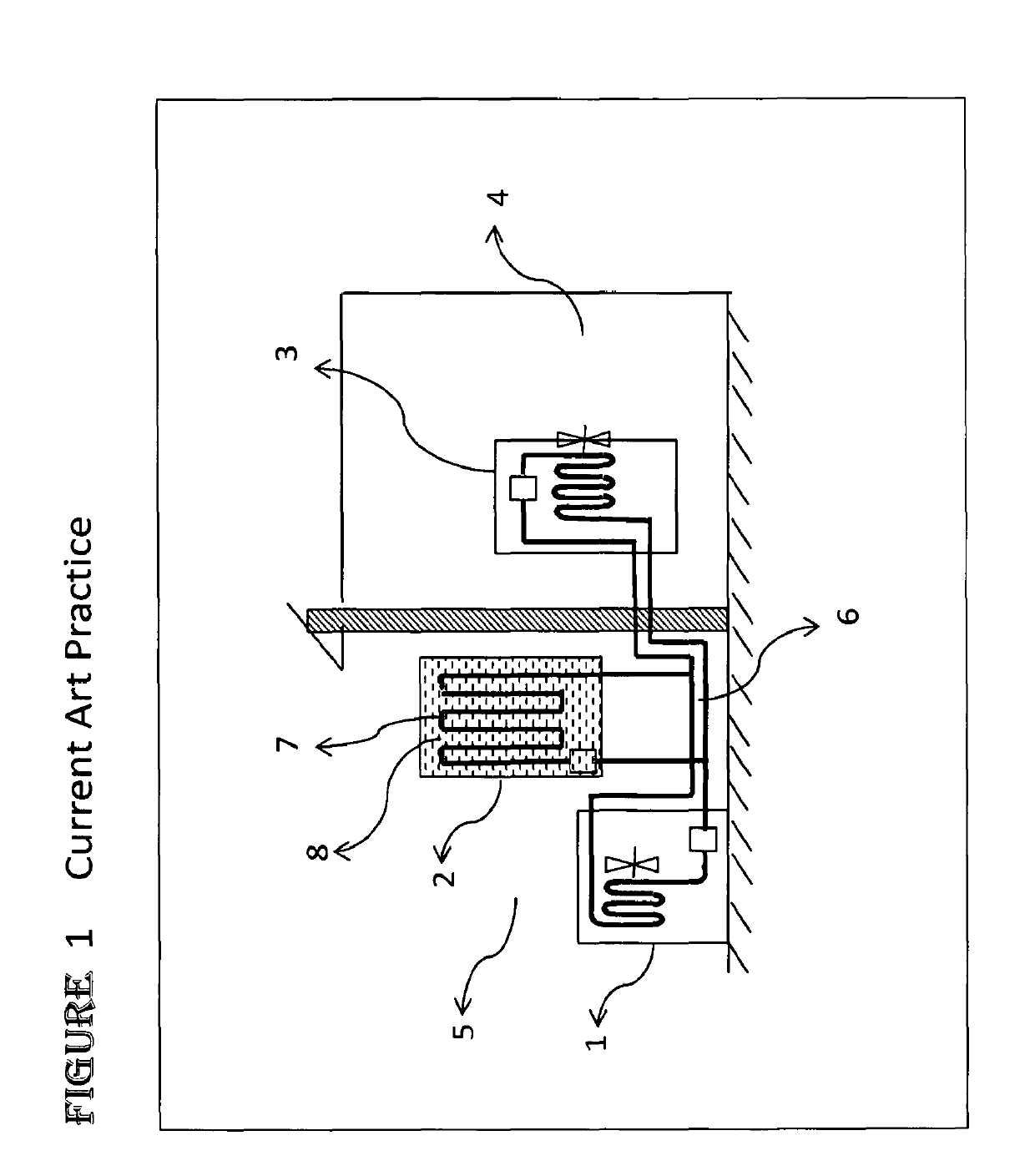
[0033]In current art, a thermal storage system charges with ice when power is available. It is subsequently run in ice-cooling mode whenever needed. The thermal storage is located outside the room-space. In ice cooling mode a refrigerant circuit is run between the thermal storage to the evaporator coils or exchanger coils to cool the room-space.

[0034]Two distinct steps are typical.—ice charging step and ice-cooling step. Ice charging can alternatively be called charging or freezing step. Ice-cooling is alternatively called room-space cooling step, ice melting step, discharging step. The charging step freezes the ice and the ice-cooling step provides cooling to the room-space by the melting ice.

[0035]A thermal storage system has a tank containing PCM. When water is used as the PCM, ice is formed when thermal storage is charged and ice is melted when the thermal storage is discharged.

[0036]In a charging mode, the water in the tank is frozen, by circulating refrigerant through it from ...


PUM


Abstract

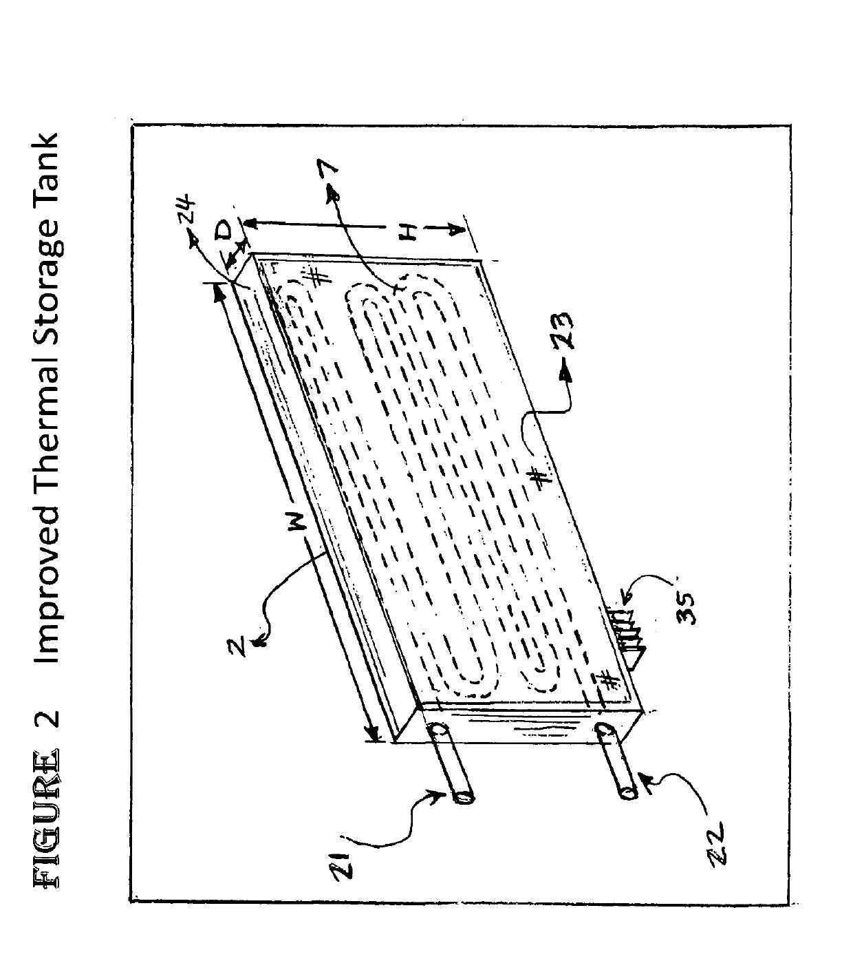
A thermal storage system, capable of storing and releasing thermal energy, with a radiative heat exchange outer surface and a method of operating the device to cool a room-space without using a circulating refrigerant in the room cooling step

Description

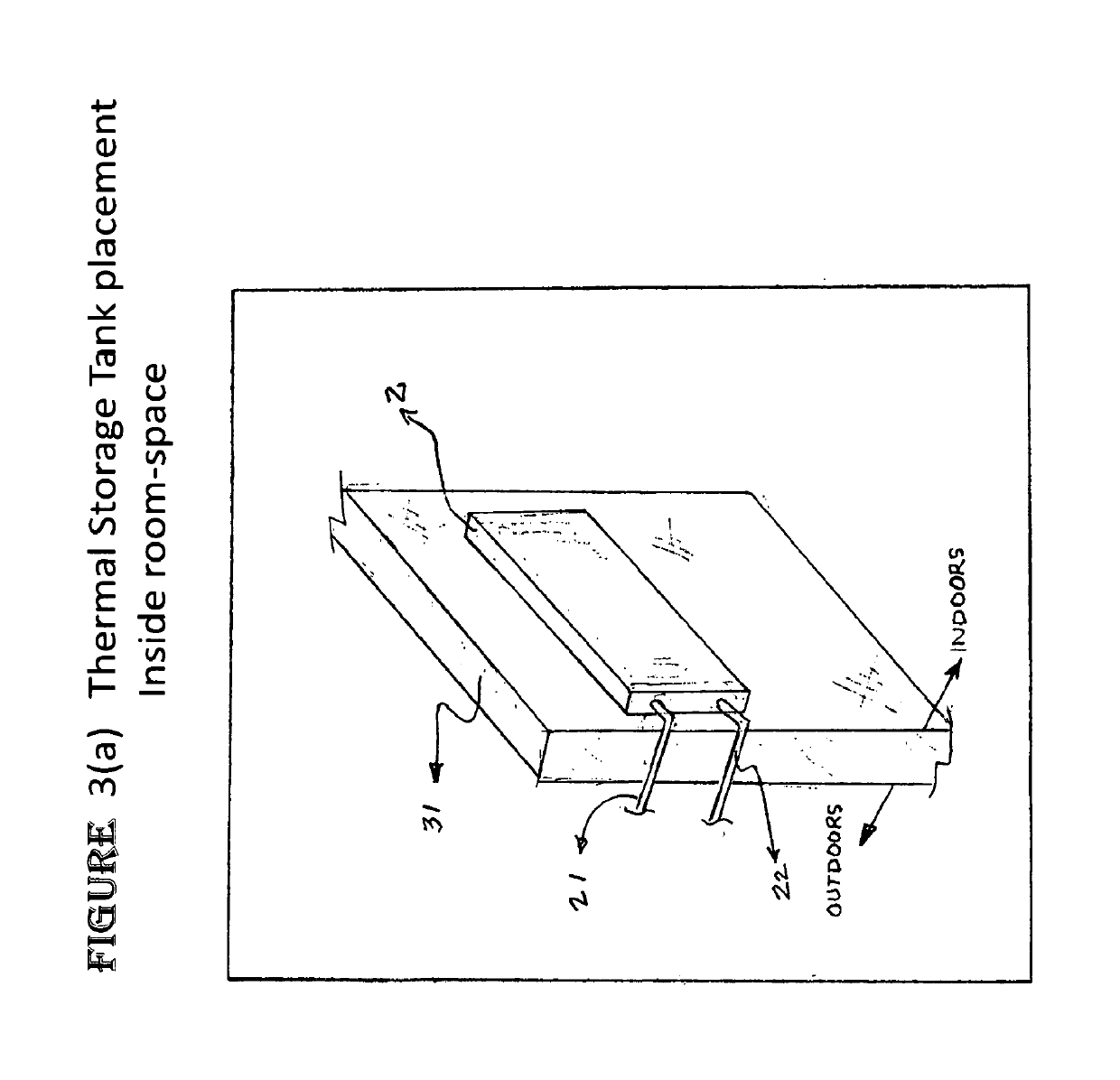
CROSS-REFERENCE TO RELATED APPLICATIONS[0001]This application claims the benefit of U.S. Provisional Patent Application No. 62 / 380,830 filed Aug. 29, 2016.FIELD OF INVENTION[0002]This invention relates to an improved design of a thermal storage tank as part of a thermal storage system to provide space conditioning to a room-space, wherein the thermal storage tank has a heat exchange surface for cooling a room-space.[0003]More specifically it provides for a novel positioning of the thermal storage tank by advantageously locating the thermal storage tank in or proximate to the room-space to be cooled.[0004]Additionally, the thermal storage system employs a refrigerant-free thermal transfer between the thermal storage in the tank and the room-space to cool the room-space.[0005]Additionally, the thermal storage tank performs cooling of a room-space with no electric power.BACKGROUND OF THE INVENTION[0006]Room conditioning equipment needs to operate on demand and preferably through all el...

Claims


Application Information

Patent Timeline
IPC IPC(8): F24F5/00
CPCF24F5/0017F24F2005/0025F25B39/02F25D16/00Y02E60/14
Inventor KAPUR, RAJANMURTHY, VIKRAMAKHAVE, JAY R
Owner TWYCE ENERGY LTD
Learn More