Image forming apparatus

Active Publication Date: 2019-06-27
CANON KK
View PDF0 Cites 0 Cited by
  • Summary
  • Abstract
  • Description
  • Claims
  • Application Information

AI Technical Summary

Benefits of technology

The present invention relates to an image forming apparatus that can control the transfer voltage regardless of the current leakage path through the transfer portion. An aspect of the invention includes the ability to detect the current flow in the transfer member and control the transfer power source to apply a predetermined voltage to the transfer member based on the detected current value. This ensures that the correct voltage is applied during the transfer process, regardless of any changes in the current leakage path. The invention also includes a fixing unit with a heating and pressing member to form a fixing portion where the transfer medium is heated and pressed to transfer the toner image onto it, with a predetermined voltage applied from the transfer power source based on a simple average value of the current detected during a predetermined time period after the transfer medium is held in the transfer portion and the first voltage is applied from the transfer power source. The technical effect of the invention is to ensure the accurate transfer of toner images onto the transfer medium, regardless of changes in the current leakage path.

Problems solved by technology

According to the arrangement discussed in Japanese Patent Application Laid-Open No. 11-219042, however, it is difficult to control the transfer voltage as appropriate, since the current leakage is undetectable if a current leakage occurs from a conductive member that is provided with no detection unit.

Method used


Image

  • Image forming apparatus
  • Image forming apparatus
  • Image forming apparatus

Examples


second exemplary embodiment

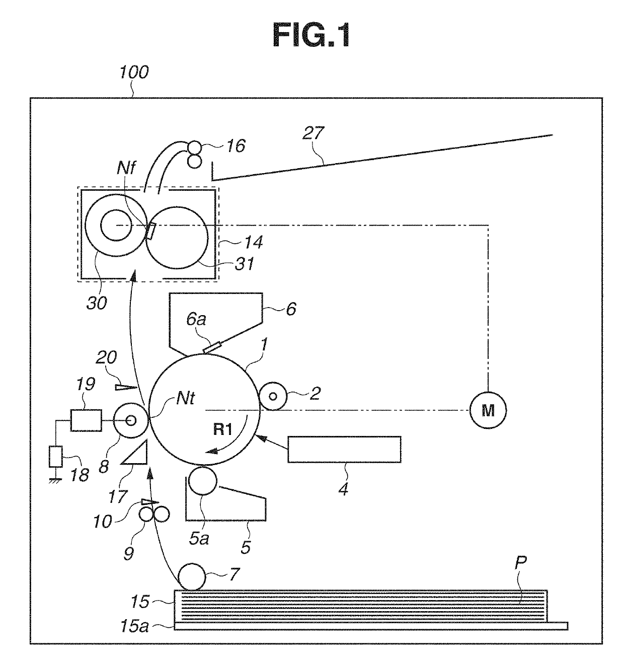
[0065]According to the first exemplary embodiment, the arrangement in which the voltage change width ΔV is set based on the current Itr detected by the detection unit 19 while the transfer medium P is held in the transfer portion Nt and the transfer voltage Vt is applied from the transfer power source 18 to the transfer roller 8, and the change width ΔV is fed back to the transfer control is described. According to a second exemplary embodiment, the voltage change width ΔV is set using a method similar to the method in the first exemplary embodiment, but the second exemplary embodiment is different from the first exemplary embodiment in that the change width ΔV is fed back to the transfer control at or after the point at which the transfer medium P reaches the fixing portion Nf. In the following description, components that are similar to those in the first exemplary embodiment are given the same reference numerals, and description of the similar components is omitted.

[0066]In the c...


PUM


Abstract

A control unit controls a transfer power source in such a manner that a current value detected by a detection unit is a predetermined value while a transfer medium is not held in a transfer portion, and the control unit sets a transfer voltage based on a voltage value applied from the transfer power source to a transfer member. Then, the transfer voltage is applied from the transfer power source to a transfer roller after the leading edge of the transfer medium in the conveyance direction for the transfer medium is held in the transfer portion and before the leading edge is held in a fixing portion. While the transfer voltage is applied, the control unit sets a voltage to be applied from the transfer power source to the transfer member based on the value of current detected by the detection unit.

Description

BACKGROUND OF THE INVENTIONField of the Invention[0001]The present disclosure generally relates to image forming apparatuses, such as copying machines, printers, and facsimile apparatuses, and more specifically to those that use an electrophotographic method or electrostatic recording method.Description of the Related Art[0002]In an electrophotographic image forming apparatus, a transfer voltage is applied to a transfer member disposed to face an image bearing member, such as a drum-shaped photosensitive member or intermediate transfer member, to electrostatically transfer a toner image borne on the image bearing member onto a transfer medium, such as a sheet or overhead projector (OHP) sheet. Thereafter, the transfer medium onto which the toner image is transferred at a transfer portion formed by the image bearing member and the transfer member is conveyed to a fixing unit and then heated and pressed by the fixing unit so that the toner image is fixed to the transfer medium.[0003]J...

Claims


Application Information

Patent Timeline
IPC IPC(8): G03G15/00G03G15/16G03G15/20
CPCG03G15/5004G03G15/162G03G15/2064G03G15/2039G03G15/0283
Inventor HARA, JUNSHIMIZU, YUSUKEIIDA, KENICHI
Owner CANON KK
Why Eureka
Try Eureka