Low-profile wearable scanning device

a scanning device and low-profile technology, applied in the field of wearable barcode readers, can solve the problems of inefficiency of productivity, readers getting caught on the edges of boxes, shelves, etc., and achieve the effect of providing flexibility of use and comfort for users

Active Publication Date: 2019-06-27
DATALOGIC USA INC
View PDF20 Cites 9 Cited by
  • Summary
  • Abstract
  • Description
  • Claims
  • Application Information

AI Technical Summary

Benefits of technology

[0003]To overcome the shortcomings of conventional wearable barcode readers that are too bulky, heavy, and cumbersome for users to wear for extended periods of time within industrial or retail environments in performing inventory picking and other tasks, a wearable barcode reader that may be segmented, have a low-profile, be light-weight, and use low-power is provided herein. The wearable barcode reader may have a flexible display and housing segment(s) to provide a user with flexibility of use and comfort when being worn. The segmented barcode reader may have different functional electronics in different segments to support the low-profile. For example, a battery may be in one segment, a flexible, low-power display in another segment, scanning unit optionally in another segment, and processing unit in yet another segment of the wearable barcode reader. A scanning unit may be integrated or separated from the wearable barcode reader.

Problems solved by technology

However, conventional wearable barcode readers are bulky as the readers tend to be inches thick, which often results in the readers getting caught on edges of boxes, shelves, or otherwise.
As a result of the thickness and configuration of wearable barcode scanners, the scanners result in a physical hassle to the user, which ultimately results in inefficiency of productivity.
Additionally, the weight and cabling of conventional wearable barcode readers are prohibitively cumbersome to the user.
As a result of the physical configurations of conventional wearable barcode readers, users tend to refrain from using the barcode readers for extended periods of time due to physical challenges and inefficiencies resulting therefrom.

Method used


Image

  • Low-profile wearable scanning device
  • Low-profile wearable scanning device
  • Low-profile wearable scanning device

Examples


Embodiment Construction

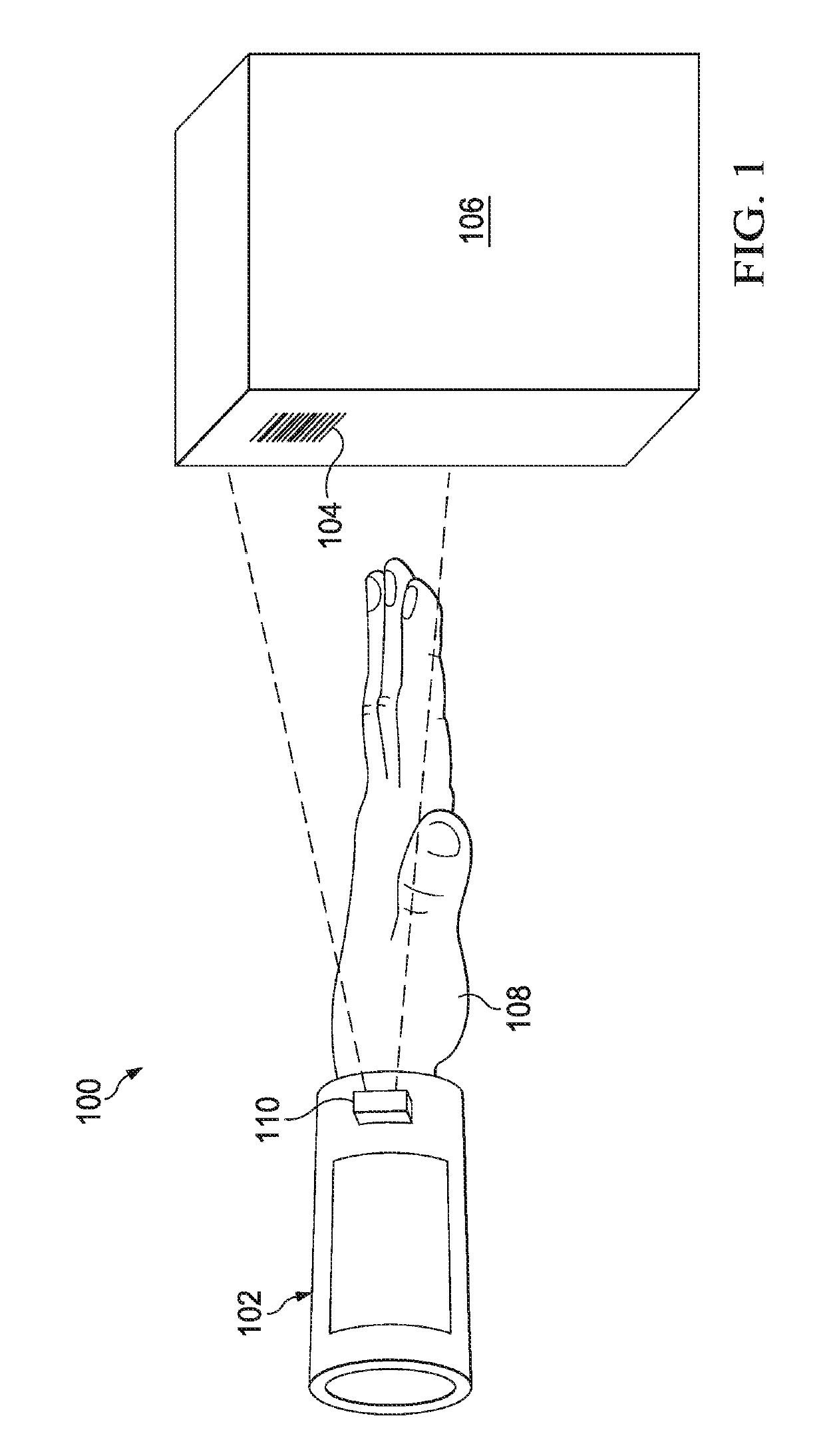
[0016]With regard to FIG. 1, an illustration of an illustrative environment 100 in which an illustrative barcode reader system 102 may be configured to read machine-readable indicia 104 is shown. The machine-readable indicia104 is disposed on an item 106, and is representative of a code associated with the item 106. In one embodiment, the wearable code reader 102 is wearable by a user 108, and configured to scan or image the machine-readable indicia 104 using a barcode scanning unit or imager 110. Embodiments of the wearable code reader 102 are described in further detail hereinbelow with regard to FIGS. 2A-7. The use of the barcode reader system 102 that is segmented, flexible, light-weight, and uses low-power provides a user with significantly more comfort and enables higher amounts of use than conventional wearable barcode readers that are bulky and heavier.

[0017]As understood in the art, a machine-readable indicia may be any symbol that is representative of a code (e.g., UPC cod...


PUM


Abstract

A code reader may include a housing configured to be wearable by a user, a scanning unit configured to scan machine-readable indicia of a target area, a user interface connected to the housing and configured to present identification data associated with the machine-readable indicia to the user, a power source disposed within the housing, a processing unit disposed within the housing, and a plurality of electrical conductors in electrical communication with the processing unit and the user interface. The processing unit may be configured to communicate a scan signal to the scanning unit to cause the scanning unit to scan the target area, receive response data from the scanning unit representative of the machine-readable indicia, generate the identification data in response to receiving the response data, and communicate the identification data to the user interface for display thereon. The electrical conductors may provide power and enable signals to be communicated.

Description

FIELD OF THE INVENTION[0001]The present invention relates to barcode readers, and more specifically, to wearable barcode readers.BACKGROUND OF THE INVENTION[0002]Barcode readers are used in a variety of ways. Barcode readers are physically configured for different uses. For example, checkout counters at points-of-sale have barcode readers that are configured to be used to scan barcodes on consumer goods, and are often fixed position and / or are handheld. For performing order picking, barcode scanners have historically be handheld in the shape of a gun with a handgrip and trigger for activating the scanner. More recently, barcode scanners have been wearable by a user to ease order picking processes, such as performing order picking in warehouses or retail stores, for example. However, conventional wearable barcode readers are bulky as the readers tend to be inches thick, which often results in the readers getting caught on edges of boxes, shelves, or otherwise. As a result of the thic...

Claims


Application Information

Patent Timeline
Patent Type & Authority Applications(United States)
IPC IPC(8): G06F1/16G06K7/10H04B1/3827
CPCG06F1/163G06K7/10891H04B1/385G06K7/10584H04B2001/3861G06F2203/0331G06F1/1686G06F3/014G06F3/0346
Inventor PAUFLER, DAVID
Owner DATALOGIC USA INC
Why Eureka
Try Eureka