
Routing method and routing device

a routing device and logistics technology, applied in the direction of navigation instruments, instruments, mechanical devices, etc., can solve the problems of increasing costs, reducing service quality, and not considering actual road traffic conditions, so as to achieve the effect of reducing distribution costs

Active Publication Date: 2019-06-27
HITACHI LTD
View PDF0 Cites 17 Cited by
  • Summary
  • Abstract
  • Description
  • Claims
  • Application Information

AI Technical Summary

Benefits of technology

The present invention provides a method and device for routing vehicles and designing networks based on road traffic conditions. The technical effects of this invention are that it can minimize costs while providing better service quality.

Problems solved by technology

However, according to Patent Documents 1 and 2, actual road traffic condition is not considered when making vehicle routing.
The travel route from the methods described in Patent Documents 1 and 2 is not an optimal route, and there is a problem of an increase in cost and a decrease in service quality.
Patent Document 3 only discloses content of generating one distribution route for one vehicle, and cannot be used to cope with the situation of multi-vehicle and multi-site that is ubiquitous in the logistics industry.

Method used


Image

  • Routing method and routing device
  • Routing method and routing device
  • Routing method and routing device

Examples


Embodiment Construction

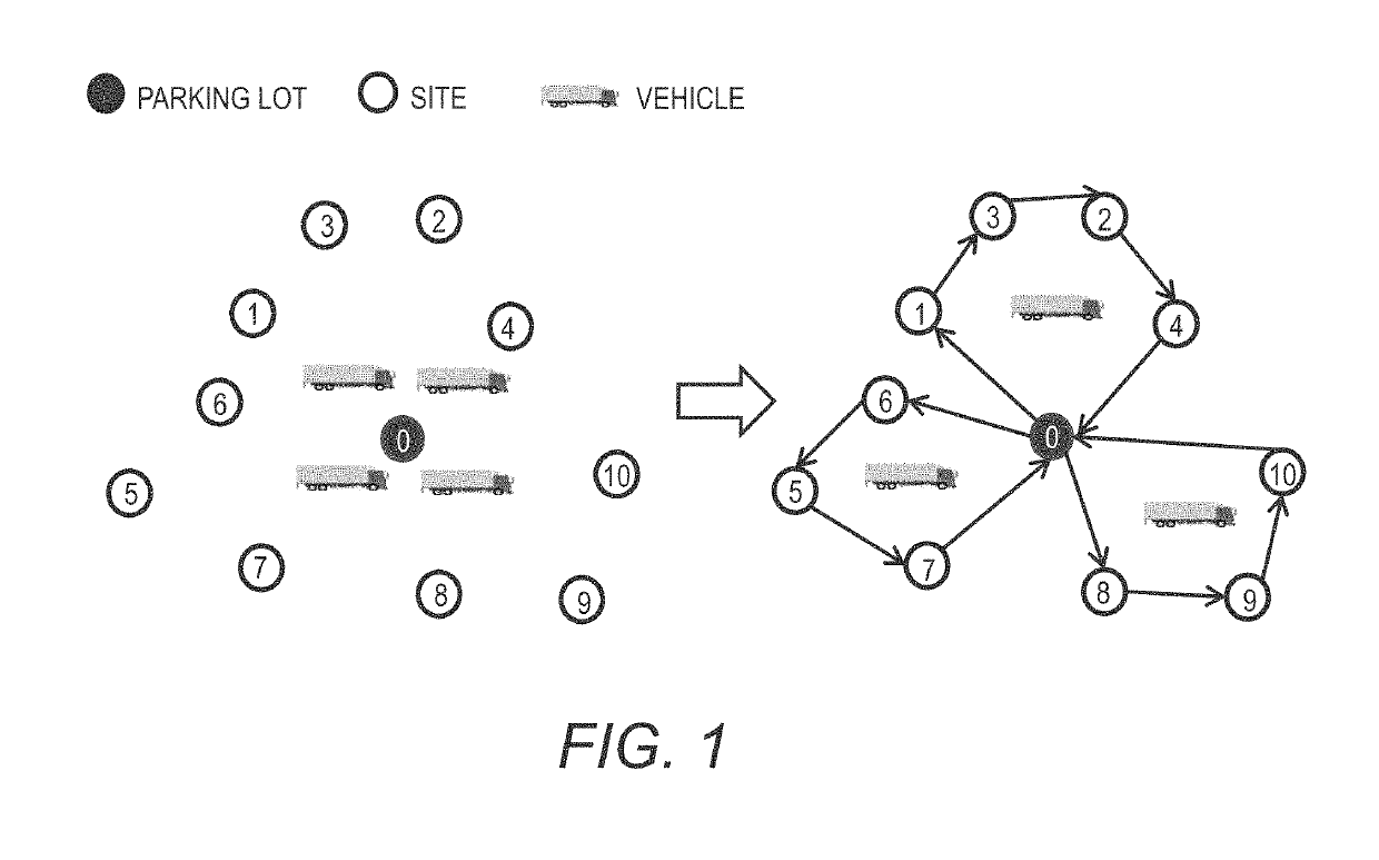
[0030]FIG. 1 is a schematic diagram showing vehicle routing for a situation of single-lot and multi-site. In FIG. 1, one parking lot, ten distribution sites and four distribution vehicles are shown. In FIG. 1, the solid circle indicates the parking lot, the hollow circles indicate the sites, the vehicle marks indicate the distribution vehicles, the solid circle with “0” also indicates the parking lot, and the numbers 1 to 10 in the hollow circles indicate different sites. However, this is only an example. The numbers of the sites and the distribution vehicles are not specifically limited and can be selected according to actual needs.

[0031]As shown in FIG. 1, through a vehicle routing, one vehicle is responsible for the distribution for the travel route of “parking lot->site 6->site 5->site 7->parking lot, the second vehicle is responsible for the distribution for the travel route of “parking lot->site 1->site 3->site 2->site 4->parking lot”, and the third vehicle is responsible for ...


PUM


Abstract

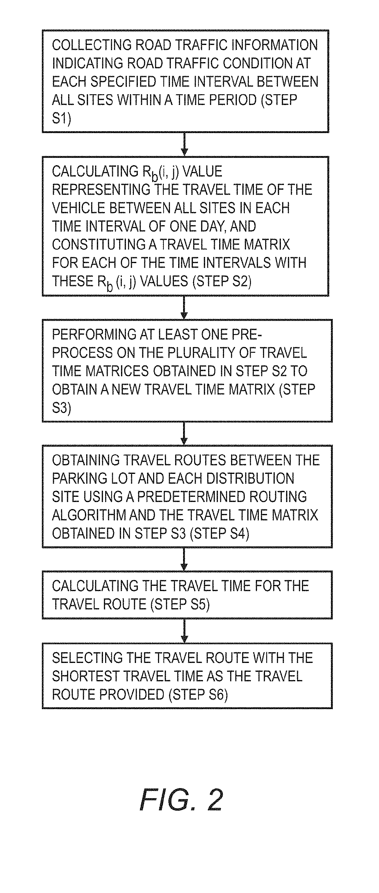
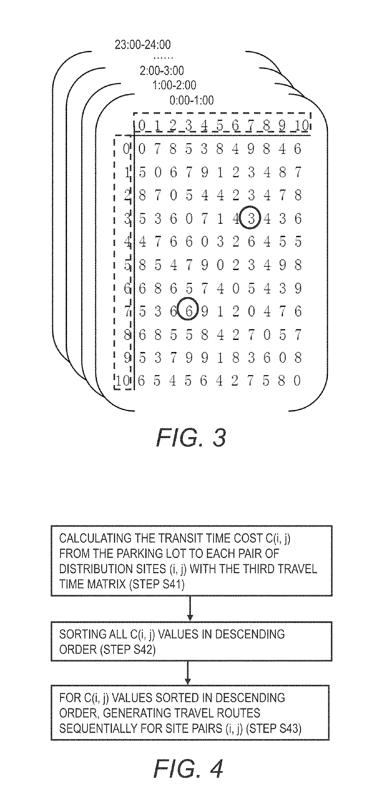
A routing method comprises: a second matrix forming step of based on first matrices indicating travel time of a vehicle between all sites in each specified time intervals in a time period forming second matrices corresponding to the specified time intervals within one day respectively; a third matrix forming step of performing a pre-process calculation on the elements at the same position in all the second matrices, and forming one third matrix with values from the pre-process calculation; a route generating step of generating a route corresponding to the pre-process based on the third matrix; and a route selecting step of: calculating a travel time for the route generated in the route generating step based on the second matrix, and selecting the route with the shortest travel time for routing the vehicle.

Description

CLAIM OF PRIORITY[0001]The present application claims priority from Chinese patent application CN 201711401079.9 filed on Dec. 22, 2017, the content of which is hereby incorporated by reference into this application.BACKGROUND OF THE INVENTION[0002]The present invention relates to routing method and routing device for vehicles in logistics, and in particular to routing method and routing device for vehicles in consideration of road traffic conditions.[0003]The logistics industry is a service industry that takes into account both cost and service quality. When providing logistics distribution services to customers, logistics service providers need to provide efficient and punctual services while minimizing the cost of services.[0004]Distribution is the key point of logistics service, which refers to the process of transporting goods from the departure place (i.e., the parking lot) to the destination (i.e., the distribution site) according to the customer's requirements on time and vo...

Claims


Application Information

Patent Timeline
Patent Type & Authority Applications(United States)
IPC IPC(8): G06Q10/04G01C21/34
CPCG06Q10/047G01C21/343G01C21/3492G01C21/3446G06Q10/08355Y02T10/40
Inventor MA
Owner HITACHI LTD
Learn More