Loading pallet

a technology of loading pallets and pallets, applied in the field of loading pallets, can solve the problems of inefficiency in commodity distribution, occupying the pallets of loading pallets, quarantine problems, etc., and achieve the effects of reducing the weight of the loading pallet, reducing the cost, and high durability

Inactive Publication Date: 2006-12-14
SHIMADA YUKO
View PDF23 Cites 16 Cited by
  • Summary
  • Abstract
  • Description
  • Claims
  • Application Information

AI Technical Summary

Benefits of technology

[0013] When the top plate, the bottom plate, and the connection unit are made of steel, the pallet with high durability can be achieved. When forming the loading pallet by corrugated boards or plastic, the weight of the loading pallet can be reduced, thereby achieving the cost reduction. In the case of the corrugated boards, particularly, they can be easily disposed of by burning them, which reduces the burden on the environment.
[0014] Further, by forming the top plates and bottom plates in a grid shape, the weight of the loading pallet can be reduced than those constructed from one piece of a plate, while it can achieve a sufficient strength.
[0015] Further, when forming the connection unit with the space retainer attached to the bottom side of the top plate and the bending elastic member for connecting the space retainer and the top side of the bottom plate, where either the bottom side of the top plate or the top side of the bottom plate or both can be attached or detached from one another, a sufficient space can be formed between the top plate and bottom plate when inserting the fork due to the existence of the space retainer. Further, by the resilient expansion and contraction of the bending elastic member that goes along with the insertion and withdrawal of the fork, a gentle and smooth approach and retreat between the top plate and bottom plate can be achieved without applying any damage to the loaded product.
[0016] Further, by constructing the connection unit with a hollow block, a sufficient space can be established between the top plate and the bottom plate when inserting the fork, and the loading pallet can be light in weight while maintaining the sufficient strength.
[0017] By having the plate-like member constructed with hollow square columns on both sides of the flat plate, the strength can be increased in comparison to a simple flat plate, and further, the loading pallet can be light in weight by having the square columns hollowed out.
[0018] By using the connecting member as a hinge or a pin and attaching it to the hollow block of the connection, a loading pallet with an easy construction and high durability, as well as able to freely attach and detach from one another can be accomplished.

Problems solved by technology

However, since its size is large, a pile of loading pallets have to occupy a large space.
Thus, there is a disadvantage of inefficiency in commodity distribution due to high storage cost and transportation cost.
Further, in the case of international commodity distribution, there is a problem involving quarantine issues since mold or insect pests tend to be parasitic on such lumber plates.
Namely, the sheet pallet involves inconveniences since a special forklift having a push-pull apparatus is required.
In addition, even if a special forklift is used, there is a disadvantage of requiring special skills of an operator since the operation is complicated.
Further, when the product is loaded and unloaded, there is a problem of damaging the surface of the product when inserting the fork.

Method used


Image

  • Loading pallet
  • Loading pallet
  • Loading pallet

Examples


first embodiment

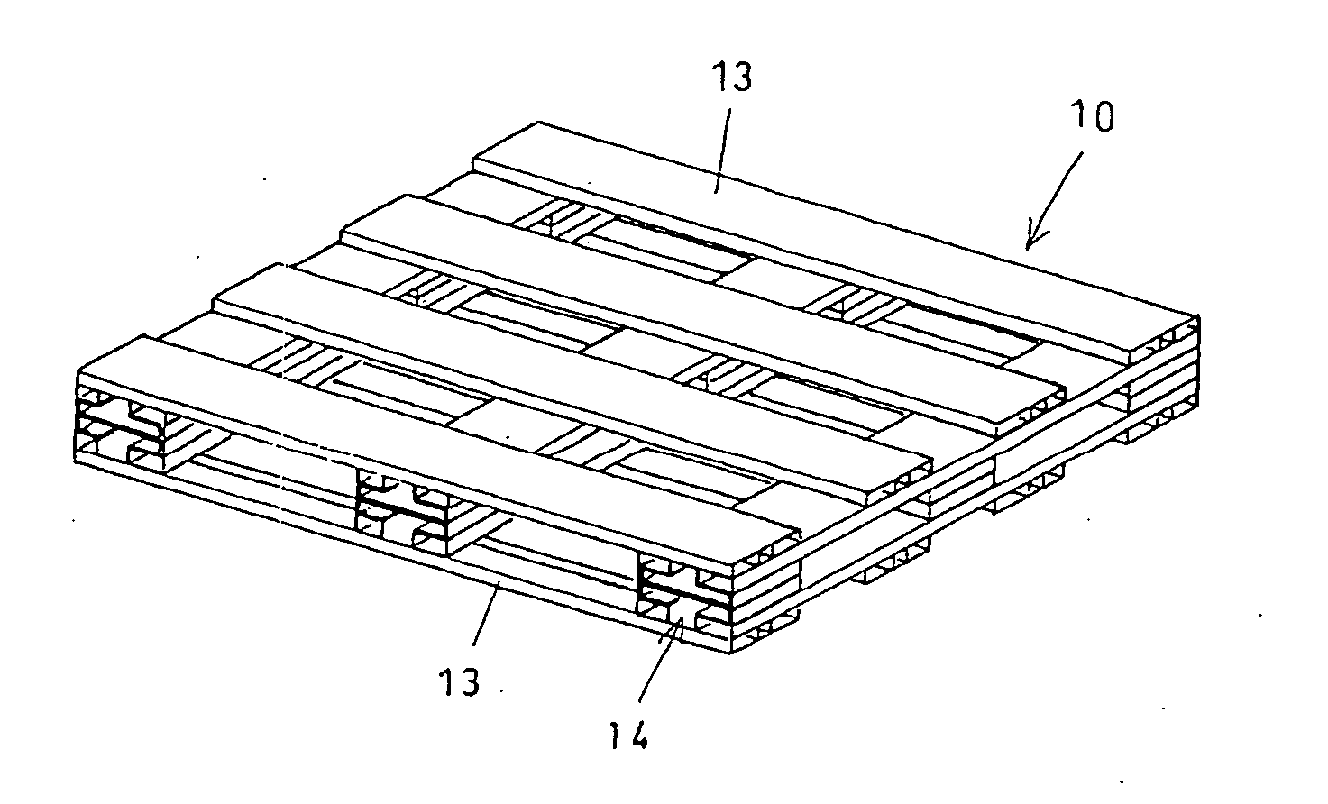
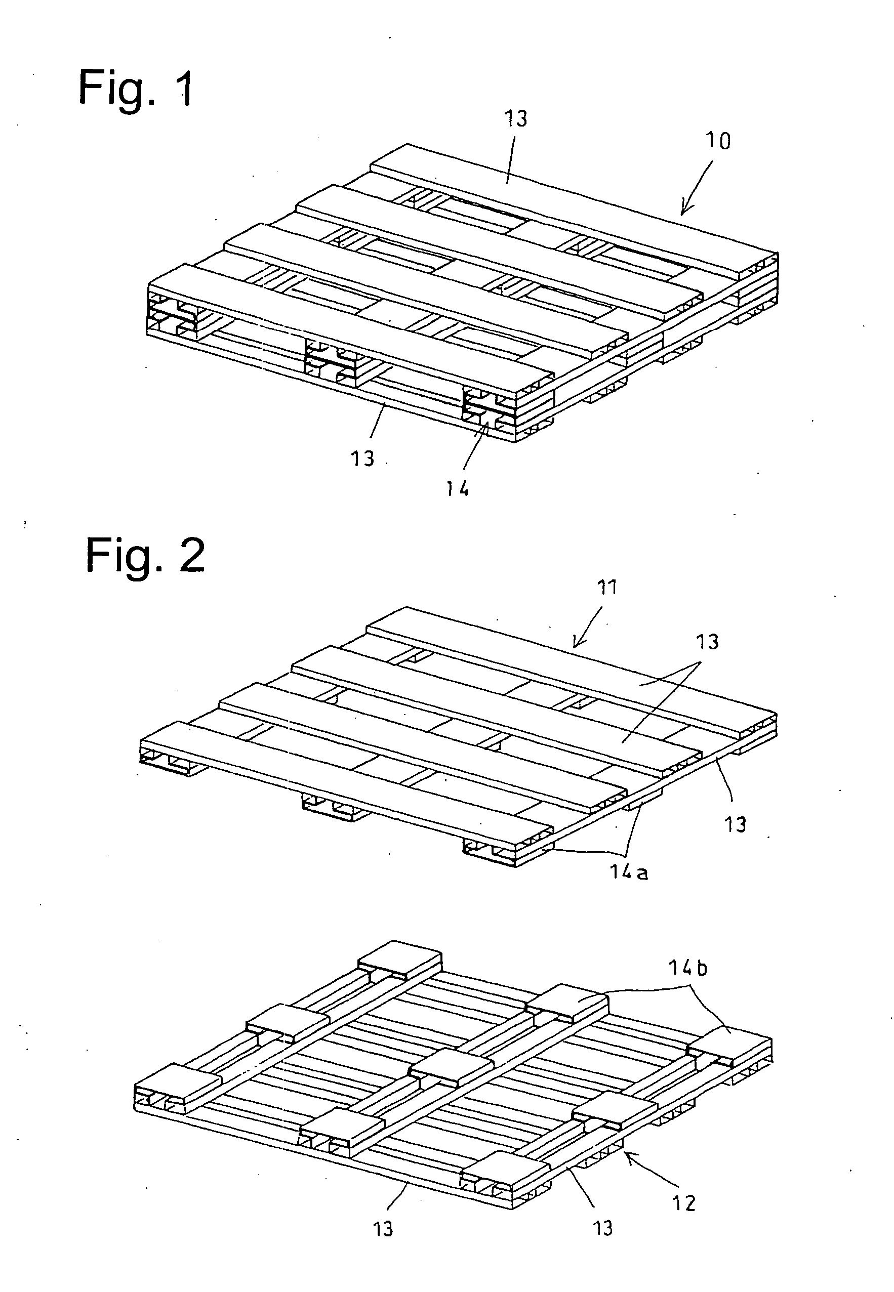
[0029]FIG. 1 is a perspective view of a loading pallet 10 in the present invention, and FIG. 2 is an enlarged perspective view thereof. As shown in these drawings, the loading pallet 10 is comprised of a top plate 11 and a bottom plate 12 each being formed by assembling a plurality of plate-like members 13 in a grid-like manner, and a connection unit 14 that connects the top and bottom plates in an attachable / detachable manner.

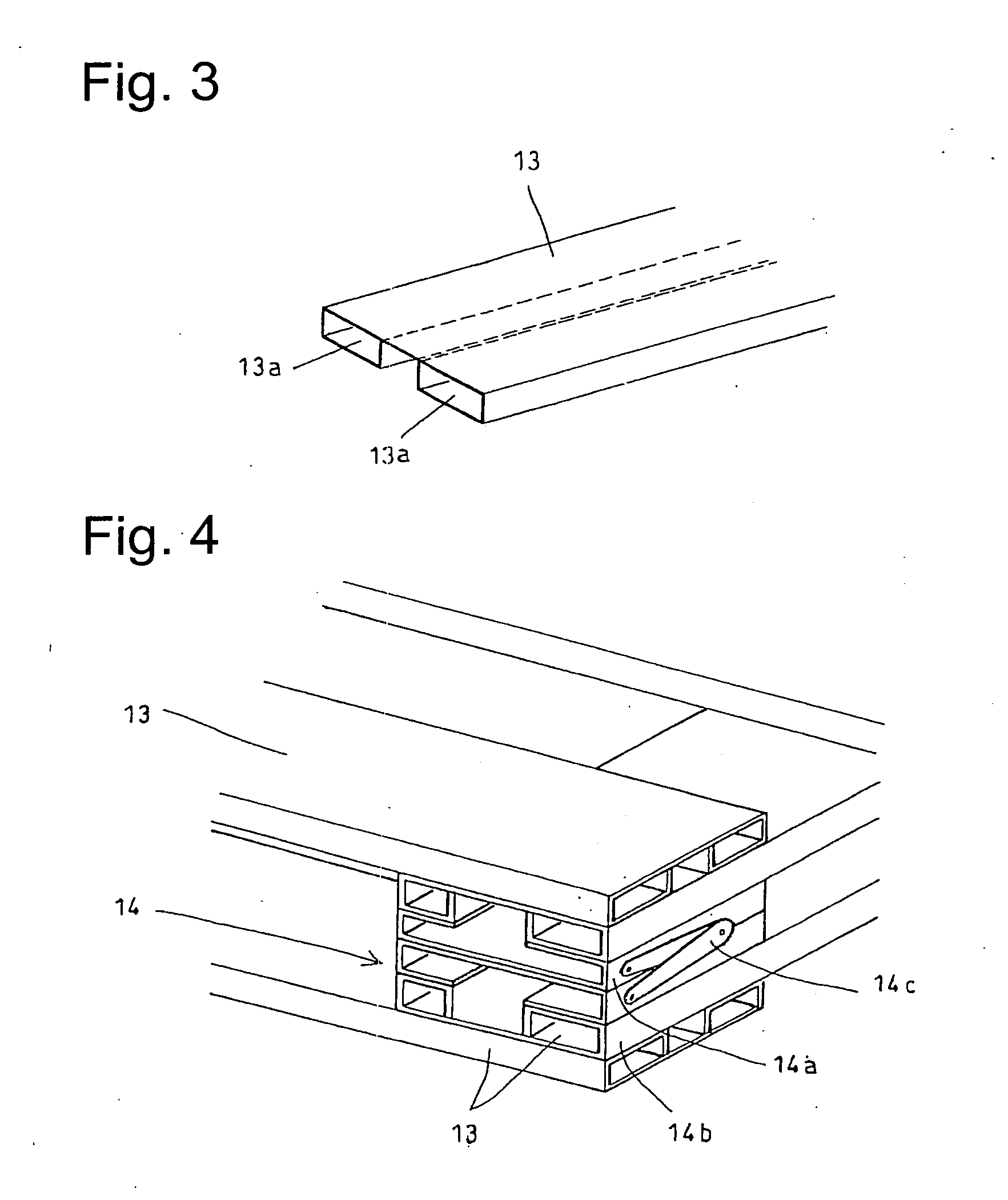
[0030] Each of the plate-like members 13, as shown in FIG. 3, is integrally established with a pair of hollow square columns 13a and 13b on both ends of the flat plate in a lengthwise direction. This plate-like member 13 can be created by folding both ends of a metal plate such as a flat steel plate into squares, thereby significantly improving the strength compared with a simple flat plate.

[0031] The top plate 11, as shown in FIG. 2, is formed by aligning the plurality of first plate-like members 13 at a predetermined space with a constant distance between o...

second embodiment

[0037]FIG. 7 shows a perspective view of a loading pallet 20 related to the present invention. The loading pallet 20, as shown in the diagram, is comprised of a flat top plate 21 and a flat bottom plate 22 and a connection unit 23 that connects the top plate 21 and the bottom plate 22 in an attachable / detachable manner. Three connection units 23 are spaced at predetermined locations so that the fork can be inserted in a space formed between the connection units 23.

[0038] The connection unit 23 is comprised of a space retainer 23a having a square shape and bonded to a bottom surface of the top plate 21, and a bending elastic member 23b for connecting the bottom of the space retainer 23a and a top surface of the bottom plate 22 as well as for connecting a bottom surface of the top plate 21 and the top surface of the bottom plate 22. The bending elastic member 23b is formed either by bending a corrugated board or plastic board in several locations or by a bending plate spring, and has ...


PUM


Abstract

A loading pallet does not require a special forklift or a large space, thereby enabling to reduce the commodity distribution cost. The loading pallet is formed of a top plate for loading the product thereon, a bottom plate for supporting the top plate thereon, and a connection unit for connecting the top plate and bottom plate in an attachable/detachable manner. The top plate, bottom plate, and connection unit are preferably made of either steel, corrugated boards, or plastic. The connection unit can extend when inserting a fork of a forklift, without requiring a special forklift, and since the connection unit shrinks when the fork is withdrawn, the loading pallet needs only a small space for storage.

Description

FIELD OF THE INVENTION [0001] This invention relates to a loading pallet for loading products thereon and transporting the products or changing the locations of the products with use of a forklift. BACKGROUND OF THE INVENTION [0002] Loading pallets for a forklift are widely used today. Typically, such a loading pallet is made of lumber and is formed by assembling the lumber plates in a grid-like manner. These loading pallets have an advantage of easy manufacturing, as well as low manufacturing cost and easy handling. However, since its size is large, a pile of loading pallets have to occupy a large space. Thus, there is a disadvantage of inefficiency in commodity distribution due to high storage cost and transportation cost. Further, in the case of international commodity distribution, there is a problem involving quarantine issues since mold or insect pests tend to be parasitic on such lumber plates. [0003] Therefore, in order to eliminate such drawbacks explained above, a sheet pa...

Claims


Application Information

Patent Timeline
Patent Type & Authority Applications(United States)
IPC IPC(8): B65D19/00
CPCB65D19/0095B65D2519/0098B65D2519/00024B65D2519/00029B65D2519/00034B65D2519/00054B65D2519/00059B65D2519/00064B65D2519/00069B65D2519/00089B65D2519/00094B65D2519/00099B65D2519/00104B65D2519/00273B65D2519/00278B65D2519/00293B65D2519/00323B65D2519/00333B65D2519/00378B65D2519/00572B65D2519/00796B65D2519/0087B65D2519/00019
Inventor SHIMADA, YUKO
Owner SHIMADA YUKO
Why Eureka
Try Eureka