Unlock instant, AI-driven research and patent intelligence for your innovation.

High flow high pressure hydraulic solenoid valve for automatic transmission

Inactive Publication Date: 2019-07-04
BORG WARNER INC
View PDF0 Cites 2 Cited by
  • Summary
  • Abstract
  • Description
  • Claims
  • Application Information

AI Technical Summary

Benefits of technology

The present invention provides a new high flow high pressure hydraulic solenoid valve for an automatic transmission. This valve can flow high flow and regulate high pressure required for controlling pulleys in the transmission. Compared to conventional systems, this valve directly controls pulley pressure and has a spool valve with specific geometry to minimize hydraulic flow forces. The valve also has hydraulic ports that balance pressure on the spool valve during high-flow conditions. These technical effects improve the performance and efficiency of automated transmissions.

Problems solved by technology

The existing valve body and valve housing design do not provide large annulus flow area around a spool valve and causes excessive side-load onto the spool valve or valve member in high pressure and high flow applications, which is undesired.

Method used


Image

  • High flow high pressure hydraulic solenoid valve for automatic transmission
  • High flow high pressure hydraulic solenoid valve for automatic transmission
  • High flow high pressure hydraulic solenoid valve for automatic transmission

Examples


Embodiment Construction

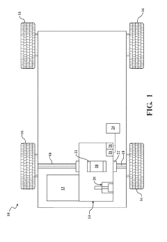
[0022]Referring now to the figures, where like numerals are used to designate like structure unless otherwise indicated, a vehicle is schematically illustrated at 10 in FIG. 1. The vehicle 10 includes an engine 12 in rotational communication with a continuously variable automatic transmission 14 of a powertrain system. The engine 12 generates rotational torque which is selectively translated to the continuously variable automatic transmission 14 which, in turn, translates rotational torque to one or more wheels, generally indicated at 16. To that end, a pair of continuously-variable joints 18 translates rotational torque from the continuously variable automatic transmission 14 to the wheels 16. It should be appreciated that the continuously variable automatic transmission 14 of FIG. 1 may be of a type employed in a conventional “transverse front wheel drivepowertrain system for the vehicle 10. It should also be appreciated that the engine 12 and / or continuously variable automatic ...


PUM


Abstract

A high flow high pressure hydraulic solenoid valve (26) includes a proportional 5 solenoid (56) and a valve body (30) operatively associated with the solenoid (56). The valve body (30) has a valve bore (32) and at least two fluid ports (38, 40) for fluid communication with the valve bore (32), wherein one of the at least two fluid ports (38, 40) includes an undercut (38b, 40b). The high flow high pressure hydraulic solenoid valve (26) also includes a valve member (42) 10 axially and slidingly disposed within the valve bore (32). The valve member (42) has a plurality of valve elements (44) spaced axially along the valve member (42). At least one of the valve elements (44) has a metering face (76a, 76c) acting with the undercut (38b, 40b). The one of the at least two fluid ports (38, 40) has two openings (82) located approximately one hundred eighty (180) degrees from each other in the valve body (30) and the valve member (42) has a control 15 module port (49a) configured to be ninety degrees from the at least one fluid port to balance pressure on the valve member (42) during high flow conditions.

Description

BACKGROUND OF INVENTION1. Field of Invention[0001]The present invention relates generally to automatic transmissions and, more specifically, to a high flow high pressure hydraulic solenoid valve for an automatic transmission.2. Description of the Related Art[0002]Conventional vehicles known in the art typically include an engine having a rotational output that provides a rotational input into a transmission such as an automatic transmission for a powertrain system of the vehicle. The transmission changes the rotational speed and torque generated by an output of the engine through a series of predetermined gearsets to transmit power to one or more wheels of the vehicle, whereby changing between the gearsets enables the vehicle to travel at different vehicle speeds for a given engine speed.[0003]In addition to changing between the gearsets, the automatic transmission is also used to modulate engagement with the engine, whereby the transmission can selectively control engagement with t...

Claims


Application Information

Patent Timeline
IPC IPC(8): F16K31/06F16K27/04F16K11/07F16H61/02
CPCF16K31/0613F16K27/048F16K11/0716F16K27/041F16H61/0251F16H2061/0253F16H2061/0255F16K2200/502F16H61/0009F16K11/07F16K31/061
Inventor ISHIHARA, MITSURUWATERSTREDT, JEFFREY J.
Owner BORG WARNER INC