Interfacing Electronic Anti-Tamper Devices with Display Elements

Active Publication Date: 2019-07-04
AVERY DENNISON CORP
View PDF3 Cites 1 Cited by
  • Summary
  • Abstract
  • Description
  • Claims
  • Application Information

AI Technical Summary

Benefits of technology

The patent describes a security component that uses an RFID component with a microchip and capacitor to create an intact circuit. This circuit is connected to a display element on the component, which indicates a change in the status of the RFID component. This change is visually different from the first state, allowing easy visualization of any tampering experienced by the anti-tamper device. The technical effect is improved security and protection against tampering.

Problems solved by technology

Unfortunately, the deactivation process does not cause a visual change in the tag.
As a result, false alarms are common as there is no visual indication of whether or not the tag has been deactivated.

Method used


Image

  • Interfacing Electronic Anti-Tamper Devices with Display Elements
  • Interfacing Electronic Anti-Tamper Devices with Display Elements

Examples


Embodiment Construction

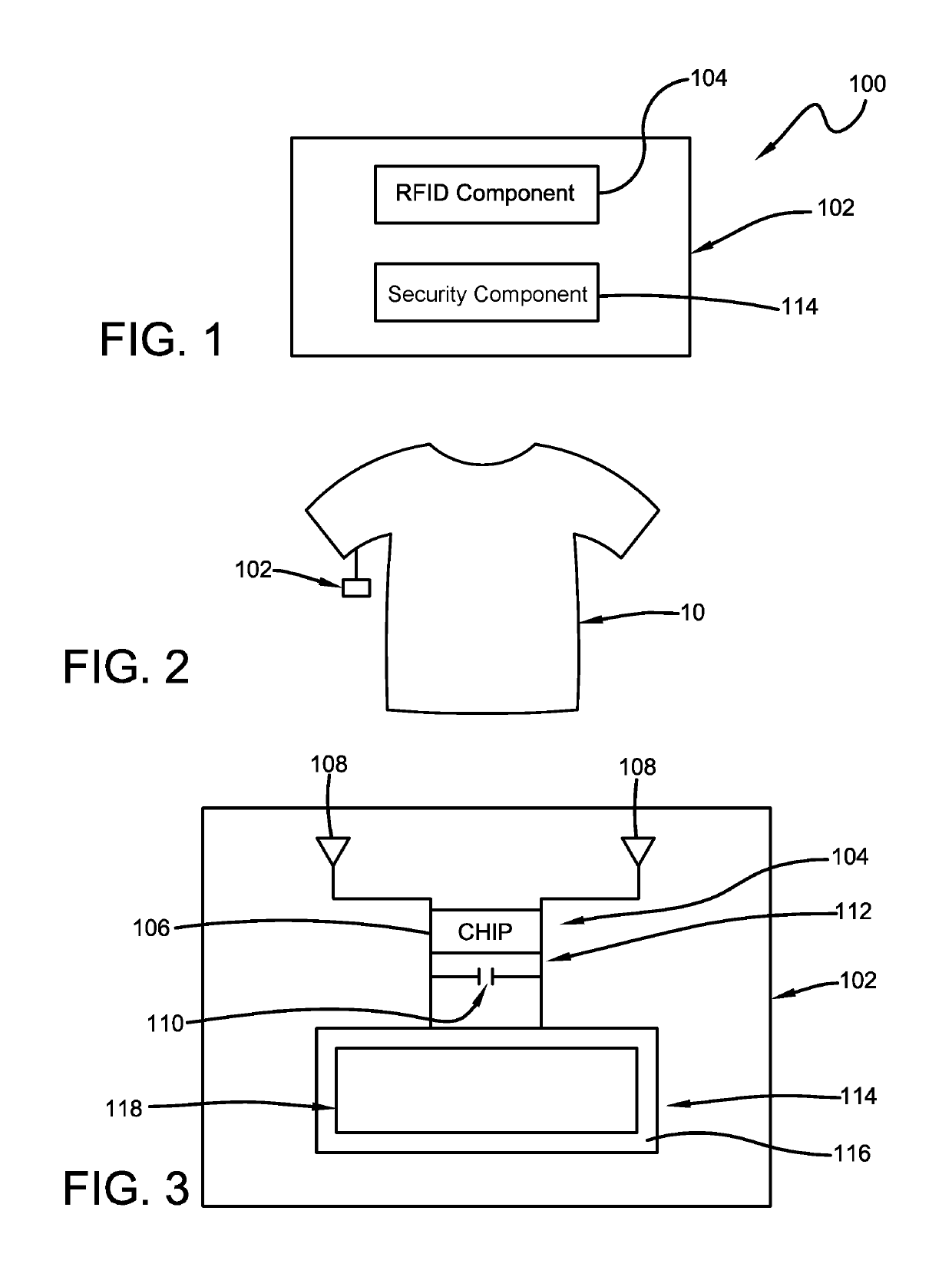
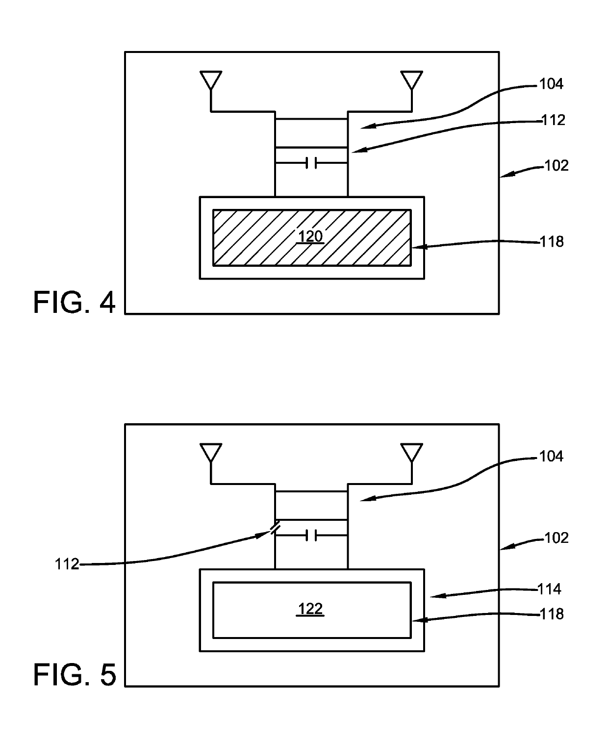
[0016]The innovation is now described with reference to the drawings, wherein like reference numerals are used to refer to like elements throughout. In the following description, for purposes of explanation, numerous specific details are set forth in order to provide a thorough understanding thereof. It may be evident, however, that the innovation can be practiced without these specific details. In other instances, well-known structures and devices are shown in block diagram form in order to facilitate a description thereof.

[0017]It is important for retailers to have a way to identify products and inventory for stock control and logistical purposes. Of equal importance to retailers is a theft control process using anti-theft features frequently referred to as article surveillance system. Such systems utilize technology to prevent shoplifting or any other unauthorized removal of property from the store setting. More specifically, electronic tags are attached to store merchandise that...


PUM


Abstract

An anti-tamper device combining a RFID component and an article surveillance or security component with a visual indicator. The article surveillance or security component is operatively coupled to a display so that an interruption of the RFID component is visibly indicated by the display. The visual indicator moves between a first state indicating a lack of tampering, and a second state indicating tampering without the need for a battery or external power source.

Description

CROSS-REFERENCE TO RELATED APPLICATION(S)[0001]The present application claims priority to and the benefit of U.S. provisional utility patent application No. 62 / 611,332 filed Dec. 28, 2017, which is incorporated herein by reference in its entirety.BACKGROUND[0002]The device of the present invention relates generally to an anti-tamper device for use in article surveillance type of applications. Specifically, the device interfaces a radio-frequency identification (“RFID”) tag having an anti-tamper capacity with a visual indicator. While the present specification makes specific reference to use of the device in article surveillance type of applications, it must be appreciated that aspects of the present inventive subject matter are also equally amenable to other like applications.[0003]RFID (Radio Frequency Identification) uses magnetic, electric or electromagnetic fields transmitted by a reader system”) to stimulate a responsive device (known as an RFID “tag” or transponder) to identif...

Claims


Application Information

Patent Timeline
IPC IPC(8): G08B13/24G02F1/137
CPCG08B13/2402G02F1/13718G06K19/0723G06K19/07372G06K19/07707
Inventor FORSTER, IAN J.
Owner AVERY DENNISON CORP
Why Eureka
Try Eureka