Blind spot warning apparatus, assembly and method
- Summary
- Abstract
- Description
- Claims
- Application Information
AI Technical Summary
Benefits of technology
Problems solved by technology
Method used
Image
Examples
Embodiment Construction
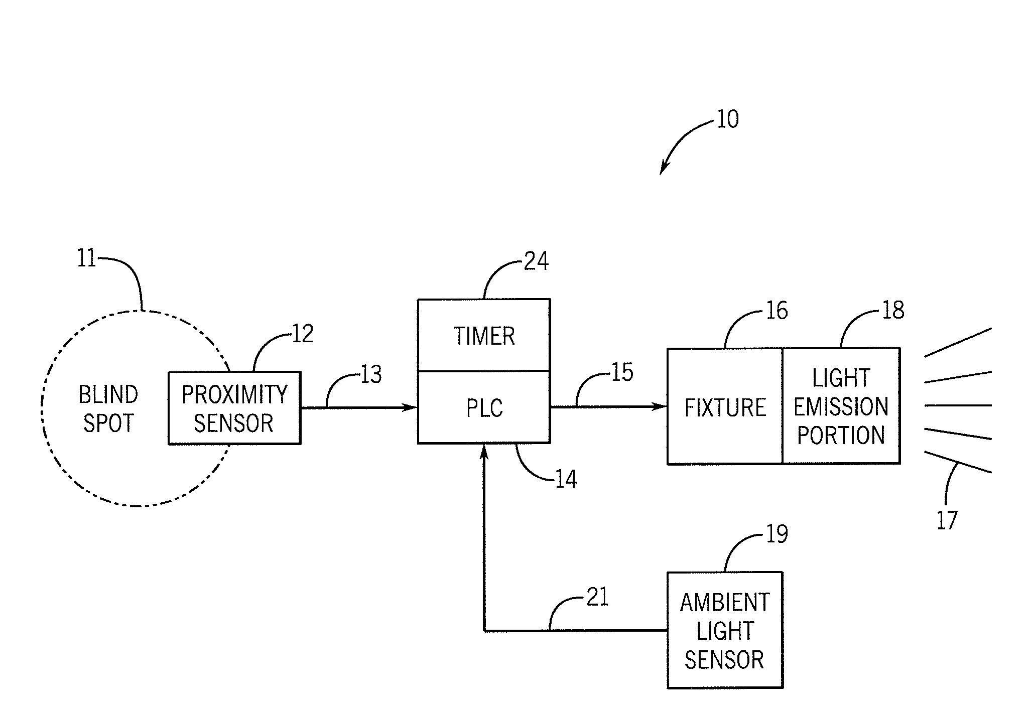
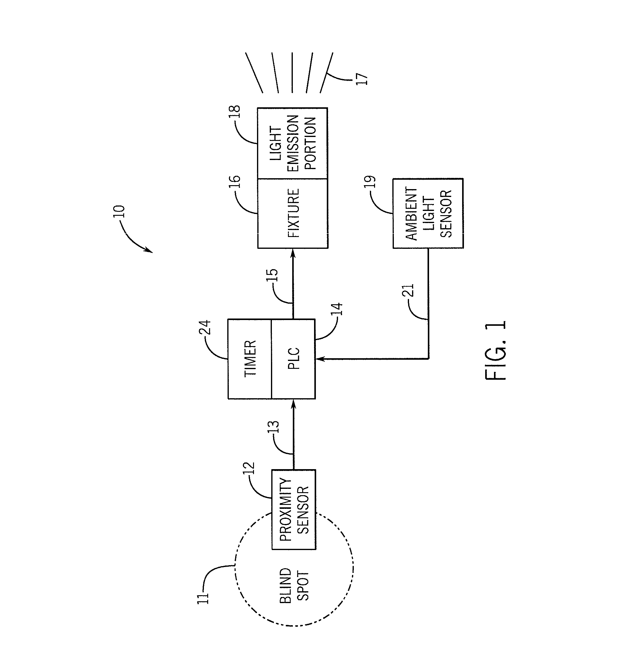
[0016]Referring now to the drawings in detail wherein like numbers represent like elements throughout, FIG. 1 illustrates a schematic view of an assembly, generally identified 10, as it would be configured in accordance with the present invention. The assembly 10 is comprised of at least one blind spot or “proximity” sensor 12, at least one PLC 14 and at least one light fixture 16, the light fixture 16 having a visual indicator or a light emission component 18 coupled to it. The sensor 12, PLC 14 and fixture 16 are each provided with an electrical supply source (not shown), such as a battery. Alternatively, the power to the assembly 10 could be provided via an electrical connection to the vehicle. The blind spot sensor 12 is positioned so as to detect the presence of a moving object (not shown) that enters a blind spot 11. The sensor 12 is electrically connected 13 to, or wirelessly in communication with, the PLC 14.
[0017]When an object enters the blind spot 11, the PLC 14 is activa...
PUM
 Abstract
Description
Claims
Application Information
 - R&D
- Intellectual Property
- Life Sciences
- Materials
- Tech Scout
- Unparalleled Data Quality
- Higher Quality Content
- 60% Fewer Hallucinations
Browse by: Latest US Patents, China's latest patents, Technical Efficacy Thesaurus, Application Domain, Technology Topic, Popular Technical Reports.
© 2025 PatSnap. All rights reserved.Legal|Privacy policy|Modern Slavery Act Transparency Statement|Sitemap|About US| Contact US: help@patsnap.com


