Prosthetic Arm With Adaptive Grip

a technology of prosthetic arms and grips, applied in the field of robotic prosthetic arms, can solve the problems of long production time, unsuitable or undesirable for many uses, and high cost of conventional upper extremity prosthetic devices

Active Publication Date: 2019-07-11
UNLTD TOMORROW INC
View PDF2 Cites 18 Cited by
  • Summary
  • Abstract
  • Description
  • Claims
  • Application Information

AI Technical Summary

Benefits of technology

[0005]According to a first aspect of the disclosure, an upper extremity prosthesis includes a prosthetic hand including a prosthetic thumb having a base and a tip and a prosthetic index finger having a base and a tip. The prosthesis may include first and second linear actuators fixedly coupled to the upper extremity prosthesis and first and second springs fixedly coupled to the upper extremity prosthesis. A first prosthetic flexion tendon may have a first end coupled to the first linear actuator and a second end coupled to the tip of the prosthetic thumb. A first prosthetic extension tendon may have a first end coupled to the first spring and a second end coupled to the tip of the prosthetic thumb. A second prosthetic flexion tendon may have a first end coupled to the second linear actuator and a second end coupled to the tip of the prosthetic index finger. A second prosthetic extension tendon may have a first end coupled to the second spring and a second end coupled to the tip of the prosthetic index finger. Upon actuation of the first linear actuator in a first direction, the first prosthetic flexion tendon causes the prosthetic thumb to flex and upon actuation of the first linear actuator in a second direction opposite the first direction, tension on the first prosthetic extension tendon provided by the first spring causes the thumb to extend. Upon actuation of the second linear actuator in the first direction, the second prosthetic flexion tendon causes the prosthetic index finger to flex, and upon actuation of the second linear actuator in the second direction, tension on the second prosthetic extension tendon provided by the second spring causes the prosthetic index finger to extend.
[0006]The prosthetic hand may include a prosthetic middle finger having a base and a tip, a prosthetic ring finger having a base and a tip, and a prosthetic pinky having a base and a tip. A third linear actuator may be fixedly coupled to the upper extremity prosthesis. Third, fourth, and fifth springs may be fixedly coupled to the upper extremity prosthesis. A third prosthetic flexion tendon may have a first end coupled to the third linear actuator and a second end coupled to the tip of the prosthetic middle finger. A fourth prosthetic flexion tendon may have a first end coupled to the third linear actuator and a second end coupled to the tip of the prosthetic ring finger. A fifth prosthetic flexion tendon may have a first end coupled to the third linear actuator and a second end coupled to the tip of the prosthetic pinky finger. Third, fourth, and fifth prosthetic extension tendons may each have a first end coupled to the third, fourth, and fifth springs, respectively, and a second end coupled to the tip of the prosthetic middle finger, prosthetic ring finger, and prosthetic pinky finger, respectively. Upon actuation of the third linear actuator in the first direction, the first, second, and third prosthetic flexion tendons may cause the prosthetic middle finger, prosthetic ring finger, and prosthetic pinky finger to flex, respectively, and upon actuation of the third linear actuator in the second direction, tension on the third, fourth, and fifth prosthetic extension tendons provided by the third, fourth, and fifth springs, respectively, causes the prosthetic middle finger, prosthetic ring finger, and prosthetic pinky finger to extend, respectively.

Problems solved by technology

Conventional upper extremity prosthetic devices can be expensive and can take a long time to produce, which may make them unsuitable or undesirable for many uses.
This generally means that the fingers have a predetermined motion path and are unable to conform to objects.
The socket creation may result in even more time and even more cost to the prosthesis.
As a result, many child amputees do not use these existing market devices.
The conventional socket system is generally created by hand and is manual labor intensive.
In order to provide a more natural appearance of the prosthesis, custom silicon gloves have been created to match the user's skin tone, but this can dramatically increase costs and the glove often wears and breaks down rapidly.

Method used


Image

  • Prosthetic Arm With Adaptive Grip
  • Prosthetic Arm With Adaptive Grip
  • Prosthetic Arm With Adaptive Grip

Examples


Embodiment Construction

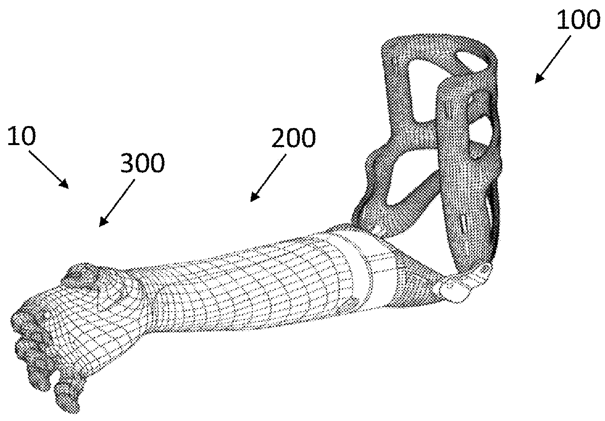
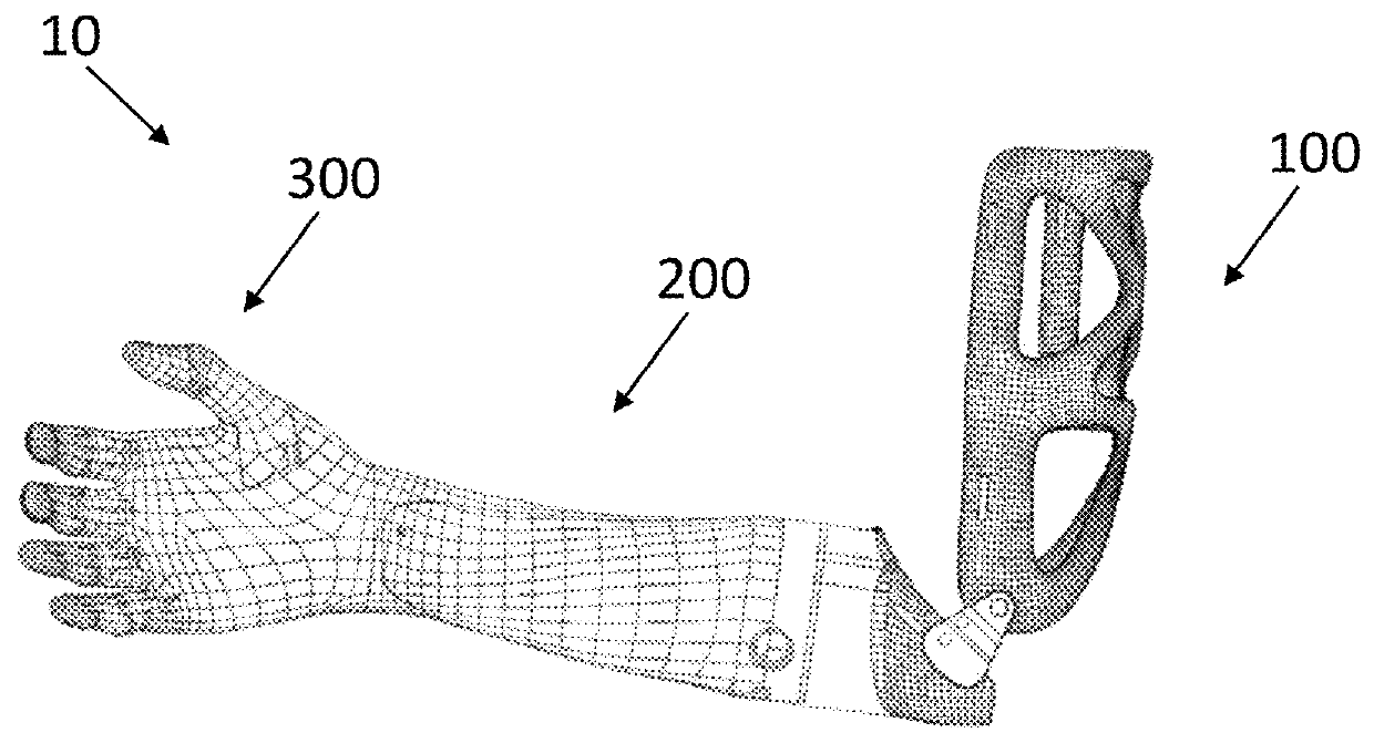
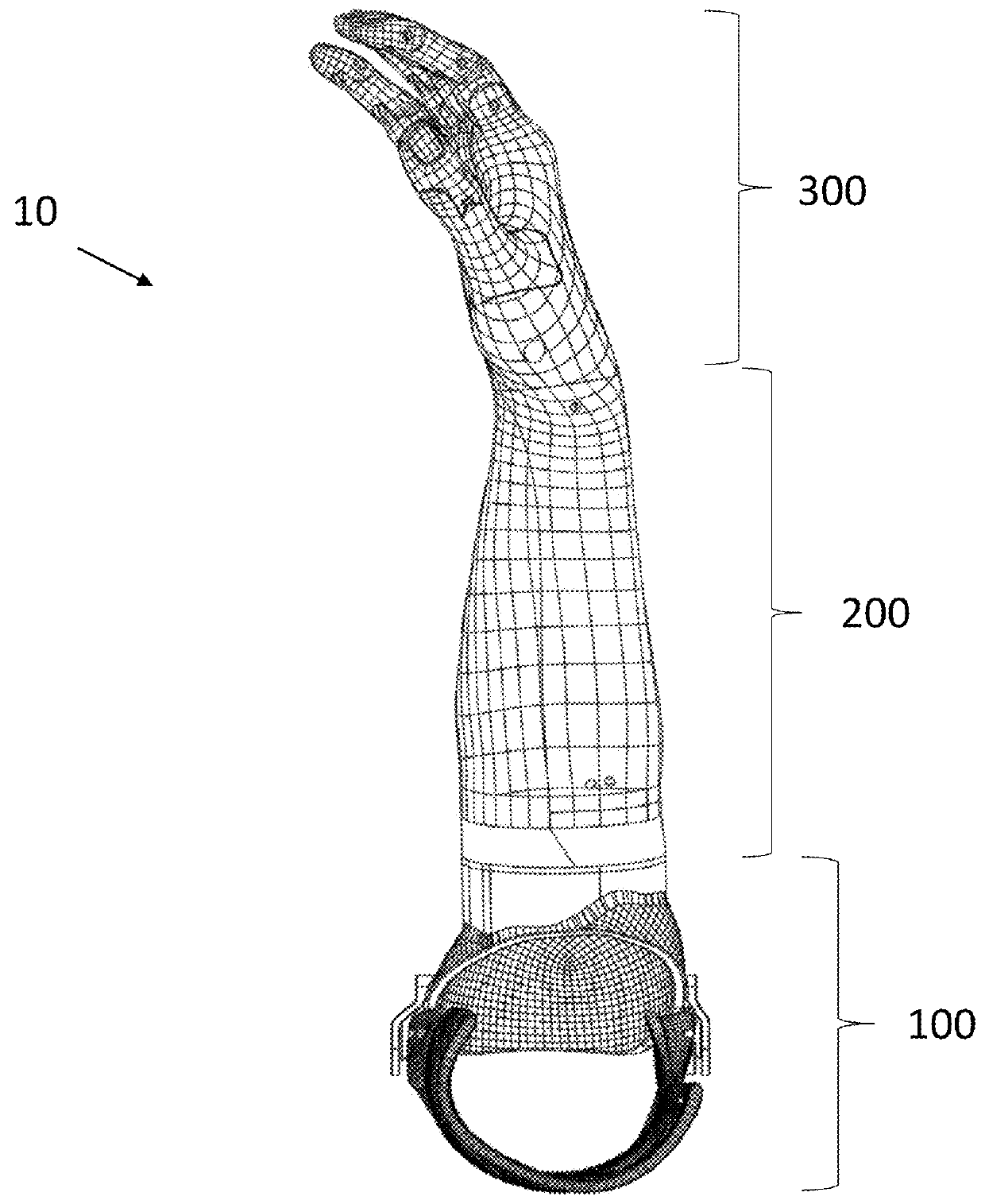
[0055]FIGS. 1A-C show an embodiment of a prosthetic upper extremity 10 for use in humans. Generally, prosthetic upper extremity 10 may include a socket 100, a prosthetic forearm 200, and a prosthetic hand 300, each of which is described in greater detail below. It should be understood that the illustrated prosthetic upper extremity 10 is for a right side of a user, but a substantially identical prosthetic upper extremity could be used for the left side of a user, with the features of the left side prosthetic extremity being substantially a mirror image of the illustrated right side prosthetic upper extremity 10.

[0056]FIGS. 2A-C show an embodiment of socket 100, which may generally function to couple the user's residual limb to the prosthetic forearm 200. Generally, socket 100 is a rigid member that matches the shape and contours of the user's residual limb, and may be attached to the residual by a compression fit or other suitable mechanism. In the illustrated embodiment, socket 100...


PUM


Abstract

An upper extremity prosthesis may include a prosthetic hand including a prosthetic thumb having a base and a tip, and a prosthetic index finger having a base and a tip. Actuators may be coupled to the upper extremity prosthesis. Prosthetic flexion tendons may have first ends operably coupled to the actuators and second ends coupled to the tips of the thumb and the index finger. Biasing systems may be operably coupled to the prosthetic thumb and the index finger. Upon actuation of the actuators in a first direction, the prosthetic flexion tendons cause the thumb and index finger to flex. Upon actuation of the linear actuators in a second direction opposite the first direction, the biasing systems cause the thumb and index finger to extend.

Description

CROSS-REFERENCE TO RELATED APPLICATIONS[0001]This application claims the benefit of the filing date of U.S. Provisional Patent Application No. 62 / 615,137 filed Jan. 9, 2018, the disclosure of which is hereby incorporated by reference herein.BACKGROUND OF THE DISCLOSURE[0002]The present disclosure is directed to robotic prosthetic arms, and particularly to patient-specific prosthetic arms with adaptive grips.[0003]Prosthetic arms have been available for use, for example by amputees, for many years. More recently, mechanical and robotic components have been introduced into prosthetic arms to provide a wide range of functionality to the prosthetic arm, for example, with individual finger joints with various mechanisms of control, including based on the user's muscle control.[0004]Conventional upper extremity prosthetic devices can be expensive and can take a long time to produce, which may make them unsuitable or undesirable for many uses. Some advanced electric hands on the market use...

Claims


Application Information

Patent Timeline
Patent Type & Authority Applications(United States)
IPC IPC(8): A61F2/58A61F2/80A61F2/68
CPCA61F2/586A61F2/80A61F2/68A61F2002/587A61F2002/6827A61F2/70A61F2002/701A61F2/72A61F2002/7635A61F2002/762A61F2002/6863A61F2002/5093A61F2/5046A61F2002/505A61F2002/6854A61F2002/764A61F2002/704A61F2002/5001A61F2002/5066A61F2002/5072A61F2/54A61F2002/543A61F2002/546A61F2/583B33Y80/00
Inventor LACHAPPELLE, EASTON J.
Owner UNLTD TOMORROW INC
Why Eureka
Try Eureka