Method for determining a motor vehicle speed profile

a technology for speed profiles and motor vehicles, applied in wave based measurement systems, instruments, data processing applications, etc., can solve problems such as inability to perform real-time calculations with an on-board computer, calculations may prove to be particularly long or even complex, and achieve simple, reliable and effective solutions.

Active Publication Date: 2019-07-11
CONTINENTAL AUTOMOTIVE FRANCE +1
View PDF0 Cites 0 Cited by
  • Summary
  • Abstract
  • Description
  • Claims
  • Application Information

AI Technical Summary

Benefits of technology

[0007]An aim of the invention is to at least partly rectify these drawbacks by proposing a simple, reliable and effective solution for calculating and providing an optimized speed profile to a driver of a motor vehicle on the basis of a predetermined route or of an event arising during driving of the vehicle.

Problems solved by technology

Such a solution therefore does not make it possible to define consumptions that are actually optimal in advance, which exhibits a major drawback.
Such calculations may prove to be particularly lengthy or even complex, which does not allow them to be performed in real time with an on-board computer, whose capabilities are limited.
In addition, the use of a predetermined speed profile does not make it possible to adapt to the occurrence of events detected over the course of the route that require a new speed profile to be recalculated when they arise.
The existing solutions do not make it possible to determine the exact speed profile for minimizing energy consumption of the vehicle for a planned route.

Method used


Image

  • Method for determining a motor vehicle speed profile
  • Method for determining a motor vehicle speed profile
  • Method for determining a motor vehicle speed profile

Examples


first example (fig.3)

First Example (FIG. 3)

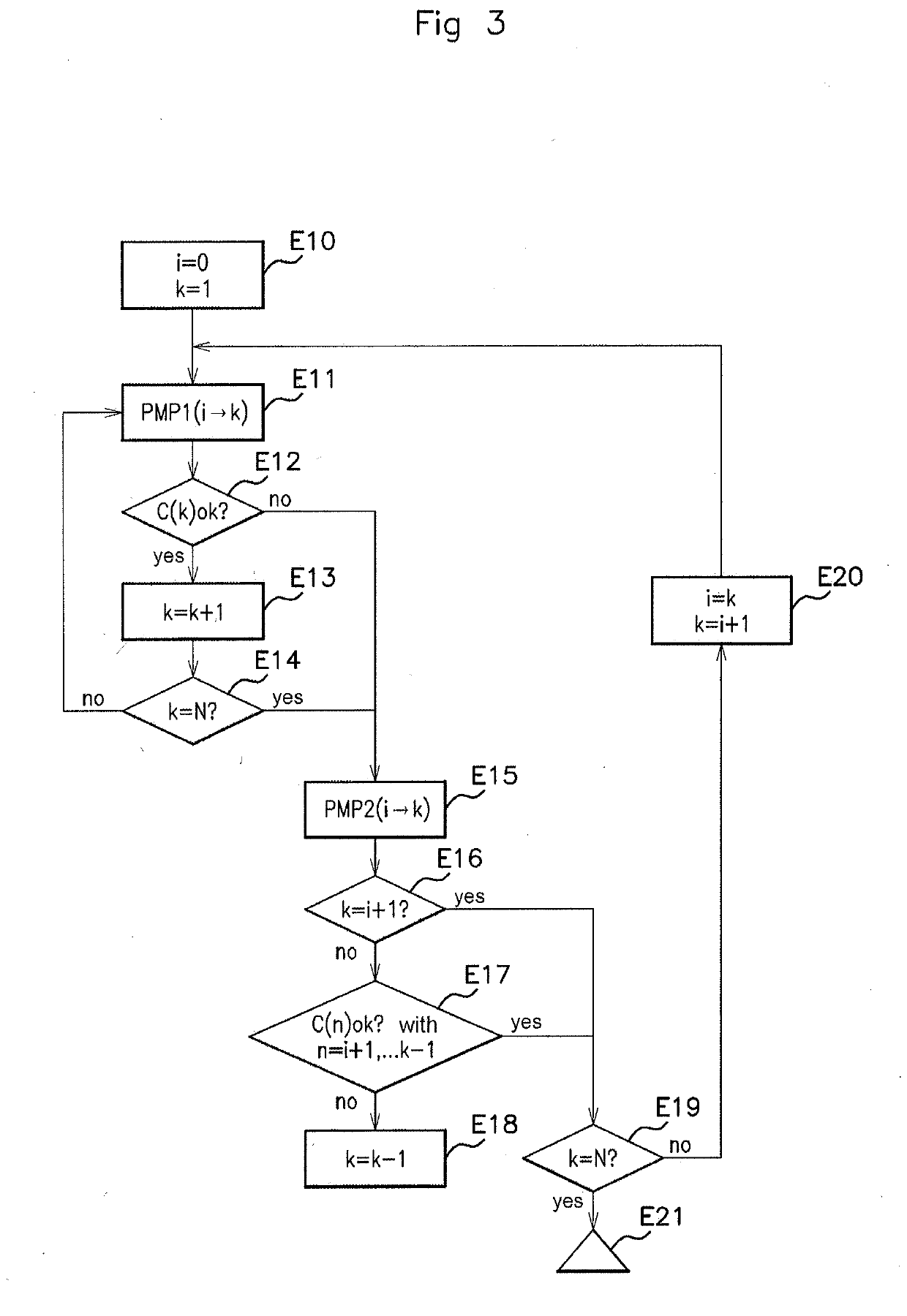
[0079]Starting from the starting point P(i=0) with k=1 (step E10), the algorithm PMP1 is first of all applied (step E11) between P(i) and P(k), and it is then checked that the speed thus calculated at the point P(k) satisfies the predetermined speed constraint C(k) at this point (step E12).

[0080]If not, we move to step E15 described below.

[0081]If so, the value of k is incremented by one unit (step E13) and it is checked whether k=N (step E14).

[0082]If there is a negative result in step E14, we return to step E11 in order to apply the algorithm PMP1 between i=0 and k, and then steps E12 to E14 are resumed.

[0083]If step E14 is affirmative, we move to step E15.

[0084]Steps E11 to E14 are thus performed for various values of k (i.e. various points P(k) of the route) until k=N or a speed constraint is not satisfied at one of the points P(k).

[0085]Starting from the point P(i), there are therefore k−i points that satisfy the constraints from C(i) to C(k) by applying P...

second example (fig.4)

Second Example (FIG. 4)

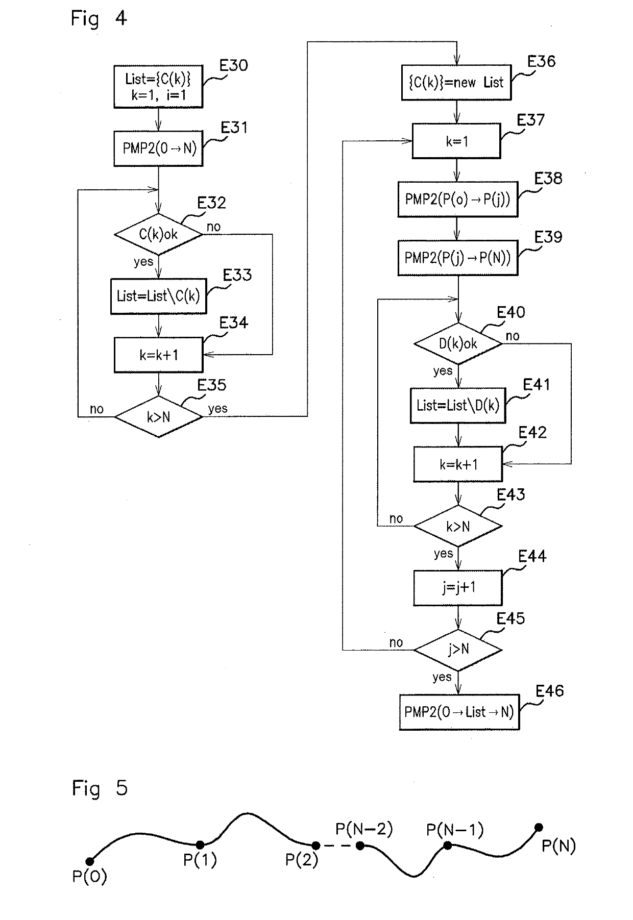
[0096]A list of the predetermined speed constraints C(k) is defined (k being between 1 and N), and then we first of all set k=1 and i=1 (step E30), and then PMP2 is applied between the starting point P(0) and the arrival point P(N) in a step E31.

[0097]It is then checked whether the speed constraint C(k) at the current point k is complied with (step E32).

[0098]If not, we move to step E34.

[0099]If so, the constraint C(k) is removed from the list of constraints (step E33), and then we move to step E34.

[0100]In step E34, the value of k is incremented by one unit, and then we move to a step E35, in which it is checked whether k is strictly greater than N.

[0101]If not, the method is resumed at step E32 with the current value of k.

[0102]If so, we move to a step E36, in which a new list of constraints D(k) is defined (k being a natural integer between 1 and N), comprising only the speed constraints that have not been complied with in step E32, in the order of the note...


PUM


Abstract

A method for determining a speed profile of a motor vehicle on a route between a starting point and an arrival point. The method includes the steps of defining a series of noteworthy points of the route, which are characterized by a stoppage of the vehicle or a decrease in the speed of the vehicle, the series of noteworthy points dividing the route into a series of portions, for each portion of the route, generating a speed and/or torque setpoint optimizing the speed profile of the vehicle by minimizing the Hamiltonian of a system of equations modeling the driving of the vehicle, and providing the setpoint generated on each portion of the route so as to optimize the driving of the vehicle up to the arrival point.

Description

CROSS REFERENCE TO RELATED APPLICATIONS[0001]This application is the U.S. National Phase Application of PCT International Application No. PCT / FR2017 / 052456, filed Sep. 14, 2017, which claims priority to French Application No. 1658636, filed Sep. 15, 2016, the contents of such applications being incorporated by reference herein.FIELD OF THE INVENTION[0002]The present invention pertains to the field of motor vehicles, and relates more particularly to a method and a device for managing the driving of a motor vehicle so as to optimize the energy consumption thereof.BACKGROUND OF THE INVENTION[0003]As is known, a motor vehicle nowadays comprises a driving assistance module for informing the driver with regard to recommended gear changes and with regard to effective speed limits over the course of the route. It is thus known to optimize gear changes so as to reduce the fuel consumption or electrical energy consumption of the vehicle for less polluting and less expensive driving.[0004]In o...

Claims


Application Information

Patent Timeline
Patent Type & Authority Applications(United States)
IPC IPC(8): B60W30/14
CPCB60W30/143G01S19/52B60W2720/103G06Q10/04G06Q10/063G06Q50/30
Inventor SANS, MARIANOSTEKKE, JORDAN
Owner CONTINENTAL AUTOMOTIVE FRANCE
Why Eureka
Try Eureka