Disparity estimation device, disparity estimation method, and program
a disparity estimation and disparity estimation technology, applied in the field of disparity estimation devices, can solve the problems of low accuracy in estimating the disparity value with sub-pixel accuracy, and the effect of more significant impact of disparity
- Summary
- Abstract
- Description
- Claims
- Application Information
AI Technical Summary
Benefits of technology
Problems solved by technology
Method used
Image
Examples
embodiment 1
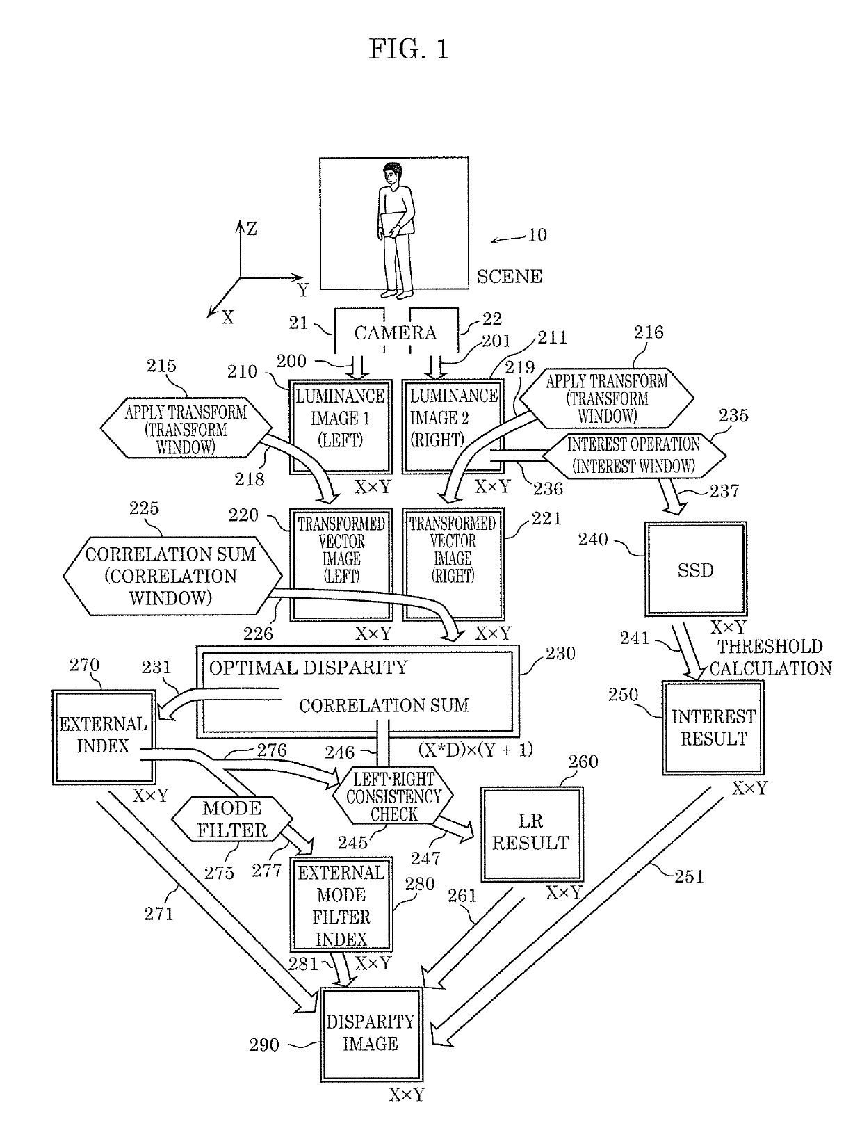
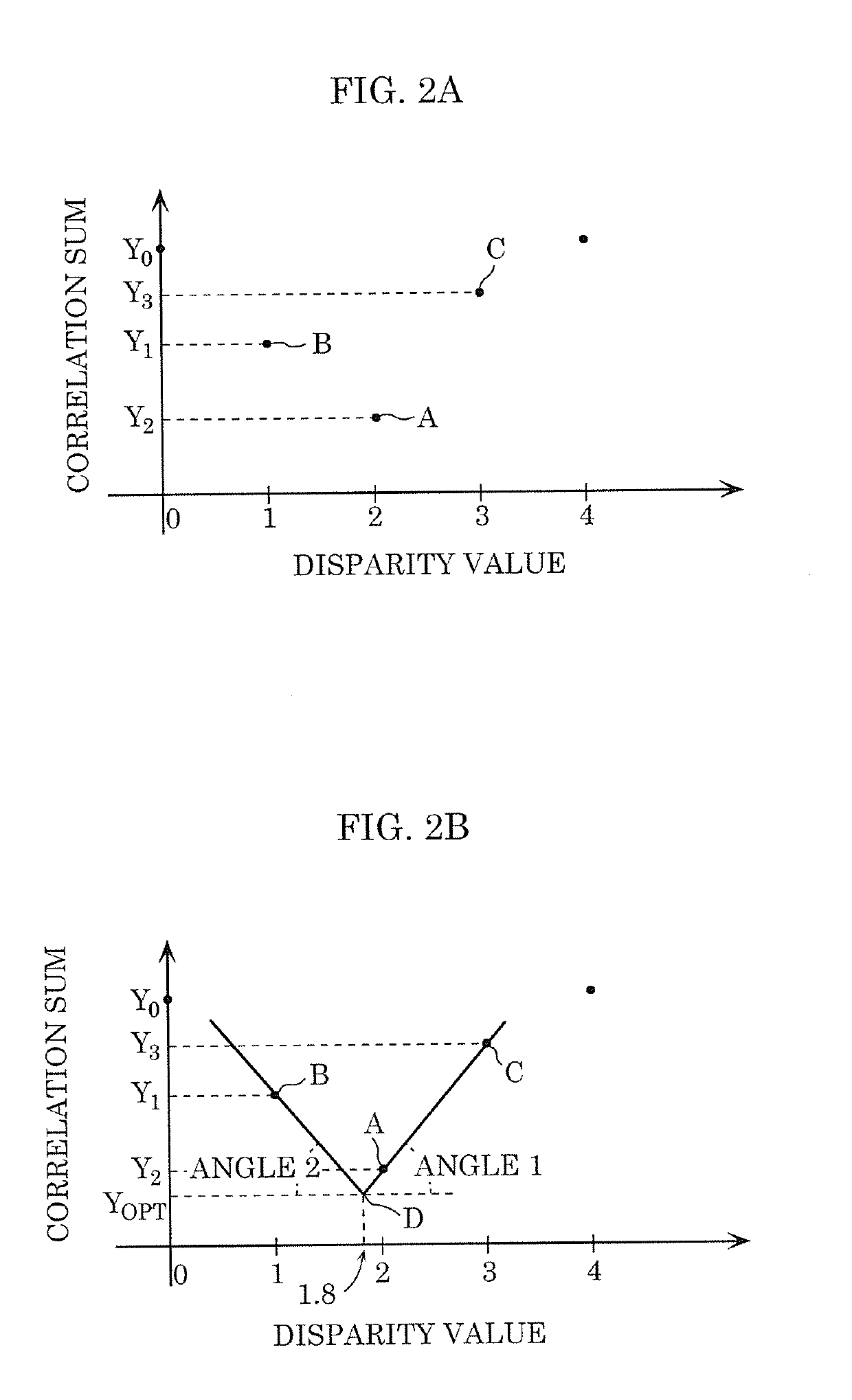
[0120]Depth measurement system 1 including disparity estimation device 100 according to Embodiment 1 will be described. Depth measurement system 1 calculates, from a plurality of captured images obtained by a plurality of cameras, the depth between a subject included in the captured images and the plurality of cameras, that is, three-dimensionally measures the depth to the position of the subject included in the captured images. Disparity estimation device 100 estimates the disparity value between the plurality of captured images to be used for the depth measurement. Note that the system capable of including disparity estimation device 100 is not limited to depth measurement system 1 and may be any system that uses the disparity value between the plurality of captured images.
[0121]FIG. 14 is a block diagram showing an example of a functional configuration of depth measurement system 1 including disparity estimation device 100 according to Embodiment 1. As shown in FIG. 14, depth mea...
embodiment 2
[0163]With disparity estimation device 100 according to Embodiment 1, the accuracy in estimating the disparity value with sub-pixel accuracy increases as the difference between the luminance values of corresponding pixels of images I1 and I2 captured by cameras 11a and 11b decreases. Disparity estimation device 200 according to Embodiment 2 further includes an element that reduces the differences between the luminance values of corresponding pixels of images I1 and I2 captured by cameras 11a and 11b. In Embodiment 2, structural elements that are substantially the same as those in Embodiment 1 will be given the same reference numerals as those in Embodiment 1, and description thereof will be omitted. The following description will focus on differences from Embodiment 1 while omitting details that are substantially the same as those in Embodiment 1.
[0164]FIG. 27 is a block diagram showing an example of a functional configuration of disparity estimation device 200 according to Embodime...
embodiment 3
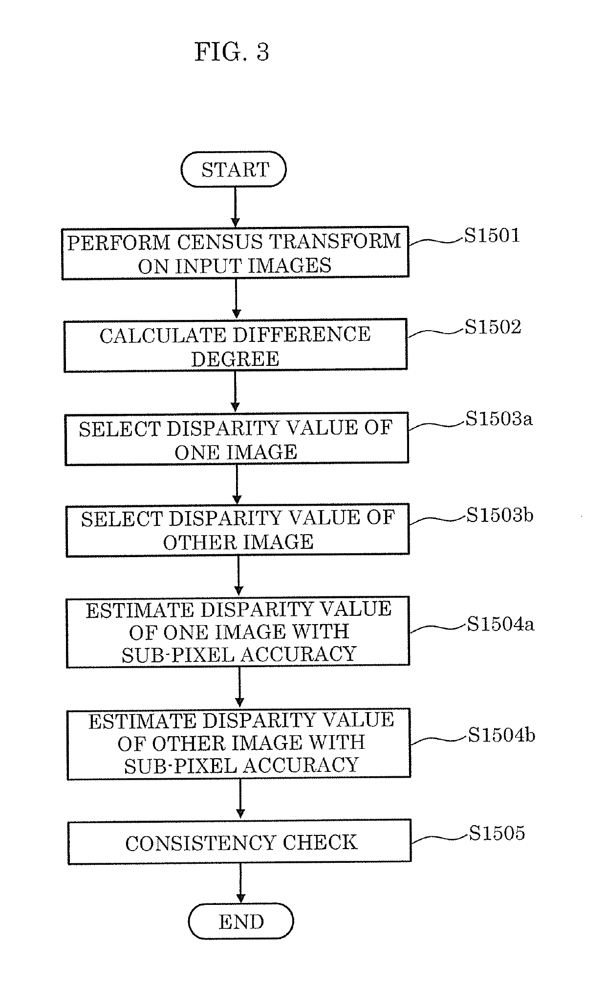
[0167]Disparity estimation device 100 according to Embodiment 1 determines one of images I1 and I2 captured by cameras 11a and 11b as the base image and the other as the reference image, and estimates the disparity values of the pixels of the base image. Disparity estimation device 300 according to Embodiment 3 determines each of captured images I1 and I2 as the base image, and compares disparity values in the base images to check the consistency of the disparity values. Specifically, disparity estimation device 300 according to Embodiment 3 estimates bidirectional disparity values and checks the consistency by comparing the estimation results of disparity values in order to improve the reliability of estimation results of disparity values, thus improving the accuracy in estimating a disparity value. In Embodiment 3, structural elements that are substantially the same as those in Embodiment 1 or 2 will be given the same reference numerals as those in Embodiment 1 or 2, and descripti...
PUM
 Abstract
Description
Claims
Application Information
 - R&D
- Intellectual Property
- Life Sciences
- Materials
- Tech Scout
- Unparalleled Data Quality
- Higher Quality Content
- 60% Fewer Hallucinations
Browse by: Latest US Patents, China's latest patents, Technical Efficacy Thesaurus, Application Domain, Technology Topic, Popular Technical Reports.
© 2025 PatSnap. All rights reserved.Legal|Privacy policy|Modern Slavery Act Transparency Statement|Sitemap|About US| Contact US: help@patsnap.com


