Optical keyswitch

a key switch and optical technology, applied in the field of optical keyswitch, can solve the problems of poor pressing feeling, easy damage to the membrane circuit, inability to meet the user's expectations, etc., and achieve the effect of reducing the interference of external light, fast and accurate triggering, and enhancing triggering accuracy

Active Publication Date: 2019-07-11
DARFON ELECTRONICS CORP
View PDF0 Cites 2 Cited by
  • Summary
  • Abstract
  • Description
  • Claims
  • Application Information

AI Technical Summary

Benefits of technology

[0026]Compared to the prior art, the optical keyswitch of the invention utilizes the emitter and the receiver as the switch unit. The optical keyswitch can be fast and accurately triggered by changing the receiving status of the optical signal and is applicable to various kinds of keyswitch structures for portable electronic devices. Moreover, the optical keyswitch of the invention optionally has the grating portion to reduce the interference of external light, so that the triggering accuracy can be enhanced and the triggering position can be suitably controlled to reduce the triggering error. Furthermore, the optical keyswitch of the invention utilizes a laterally movable component or portion to change the received intensity of the optical signal, so the space requirement in the vertical direction (i.e. the thickness direction) can be effectively reduced.

Problems solved by technology

However, the membrane circuit is easily damaged and difficult to repair when it is frequently used or operated by improper forces.
Moreover, when the user presses the keycap to trigger the membrane circuit, the tactile feedback is less significant, which causes the pressing feeling to be poor and cannot satisfy the user's expectation.
However, the metal piece and the metal contact are easily worn out due to operation impact, which reduces the life of the keyswitch.
The metal piece and the metal contact are also prone to rusty, resulting in poor conduction, which affects the operation stability of the keyswitch.
Moreover, conventional mechanical keyswitches are more complicate in structure and bigger in volume and not suitable for portable electronic devices having higher thinning requirements, such as laptop computer.

Method used


Image

  • Optical keyswitch
  • Optical keyswitch
  • Optical keyswitch

Examples


first embodiment

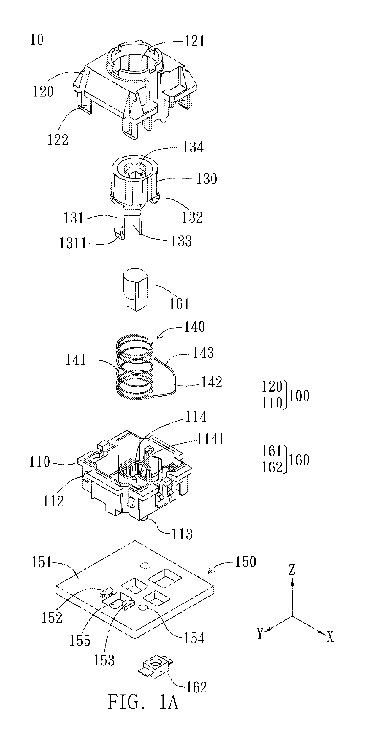
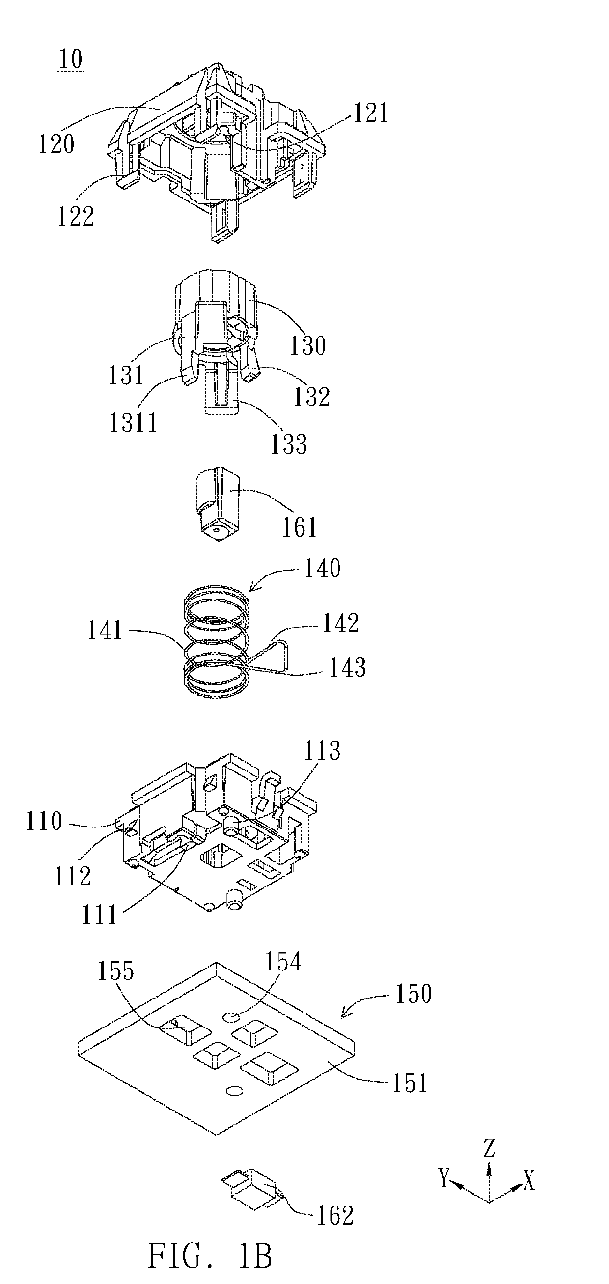
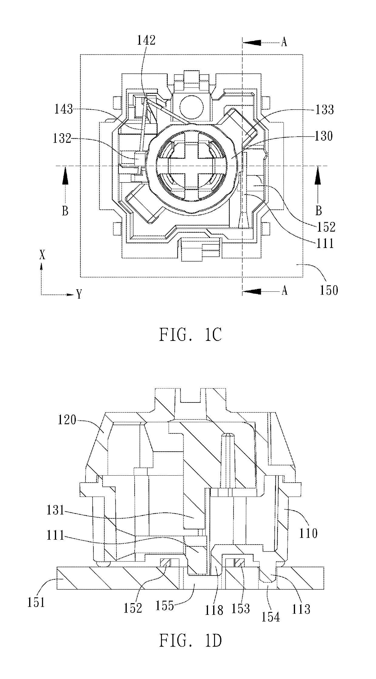
[0065]FIGS. 1A to 5D are schematic views of the invention, wherein FIGS. 1A and 1B are exploded views of the optical keyswitch from different viewing angles, FIG. 10 is a schematic top view of the optical keyswitch of FIG. 1A without the upper casing, and FIG. 1D is a cross-sectional view of FIG. 10 along the cutting line AA with the upper casing. As shown in FIGS. 1A to 1D, the optical keyswitch 10 includes a casing 100, a shaft 130, a resilient member 140, and a switch module 150. The casing 100 has a movable portion 111. The shaft 130 is movably disposed on the casing 100. In response to a pressing force, the shaft 130 can move along an up-down path from a non-pressed position to a pressed position. The resilient member 140 is accommodated in the casing 100. The resilient member 140 couples the shaft 130 and enables the shaft 130 to return to the non-pressed position when the pressing force is released. The switch module 150 includes a circuit board 151, an emitter 152, and a rec...

fifth embodiment

[0104]FIGS. 10 to 12B are schematic views of the invention.

[0105]FIG. 10 is an exploded view of the optical keyswitch, FIGS. 11A and 11B are respectively schematic views of the upper casing and the lower casing of FIG. 10, and FIGS. 12A and 12B are respectively a top view and a perspective view of the optical keyswitch of FIG. 10 without the keycap. As shown in FIGS. 10 to 12B, the optical keyswitch 30 of the fifth embodiment includes a keycap 310, a support mechanism 320, a restoring mechanism 330, a switch module 340, and a baseplate 350. The support mechanism 320 is disposed below the keycap 310 and configured to support the keycap 310 moving upward and downward. The support mechanism 320 has a protrusion 323. The restoring mechanism 330 is disposed below the keycap 310 and configured to provide a restoring force to enable the keycap 310 to return to a non-pressed position. The restoring mechanism 330 includes a casing 331 and a resilient member 332. The casing 331 has a movable ...

sixth embodiment

[0128]Referring to FIGS. 15A and 15B, the operation of the optical keyswitch 30′ of the sixth embodiment will be illustrated. As shown in FIGS. 15A and 15B, when the keycap 310 is not pressed, the protrusion 323 at least partially overlaps the movable portion 338 in a direction parallel to a moving direction of the keycap 310, such as the Z axis direction, the movable portion 338 has the first spatial relation with the optical path, and the receiver 343 receives the optical signal of first intensity. When the keycap 310 is pressed, the resilient member 332 is compressed, and the support mechanism 320 is driven to move along with the keycap 310, so that the protrusion 323 pushes the movable portion 338 to move, the movable portion 338 no longer has the first spatial relation with the optical path, and the optical signal received by the receiver 343 has the second intensity different from the first intensity. As such, the switch module 340 is triggered to generate the triggering signa...


PUM


Abstract

An optical keyswitch includes a casing having a movable portion, a shaft movably disposed on the casing, a resilient member accommodated in the casing, and a switch module including a circuit board, an emitter, and a receiver. The emitter emits an optical signal along an optical path to the receiver. When the shaft is at a non-pressed position, the movable portion has a first spatial relation with the optical path, and the receiver receives the optical signal of a first intensity. When the shaft moves, in response to a pressing force, to a pressed position, the shaft compresses the resilient member and pushes the movable portion to move, so the movable portion no longer has the first spatial relation with the optical path, the optical signal received by the receiver has a second intensity different from the first intensity, and the switch module is triggered to generate a triggering signal.

Description

BACKGROUND OF THE INVENTION1. Field of the Invention[0001]The invention generally relates to an optical keyswitch. Particularly, the invention relates to an optical keyswitch which is triggered according to the receiving status of the optical signal.2. Description of the Prior Art[0002]Membrane keyswitches and mechanical keyswitches are common types of keyswitch for keyboards. The major difference between the membrane keyswitch and the mechanical keyswitch is the circuit structure for generating the triggering signal. In general, the membrane keyswitch utilizes the membrane circuit as a switch for generating the triggering signal. When the keycap is pressed to trigger the membrane circuit, the upper circuit layer is deformed to enable the upper switch contact of the upper circuit layer to contact the corresponding lower switch contact of the lower circuit layer, so the membrane circuit is conducted to generate the signal. However, the membrane circuit is easily damaged and difficult...

Claims


Application Information

Patent Timeline
Patent Type & Authority Applications(United States)
IPC IPC(8): H03K17/968G01J1/02
CPCH03K17/968G01J1/0238
Inventor WANG, YUNG-CHIHHSIEH, YU-CHUNYANG, CHENLIU, CHIA-HUNG
Owner DARFON ELECTRONICS CORP
Why Eureka
Try Eureka